Getting started with ITALA® cameras
Connecting your camera to the lens
Power up the camera
Connect ethernet cable to a network card
Download and install ITALA SDK and ITALA View
IP settings
Setting the network interface card (NIC)
Updating the firmware
In this chapter, you will find all the steps needed to set up your ITALA® camera.
If it is your first time setting up an ITALA® camera, this is the perfect place to start.
Just keep in mind that the following steps aim to provide a practical guide to easily start operating a generic ITALA® camera. To dive deep into further technical information or if you need detailed information about a specific ITALA® camera, we recommend you always refer to the detailed camera manual, technical documentation or to get in contact with our technical support.
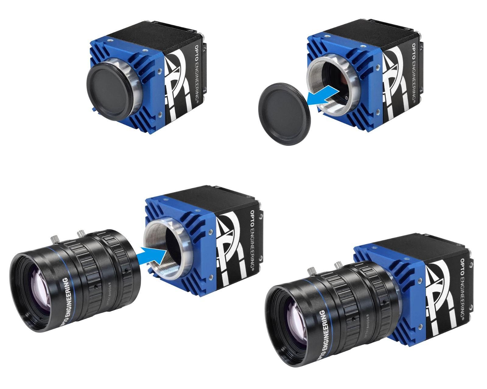
Connecting your camera to the lens
Inside of your camera package you should find a camera with an attached dust cap. Please note that cables and POE power sources are not included.
Remove the dust cap and screw on a compatible lens into the camera mount.
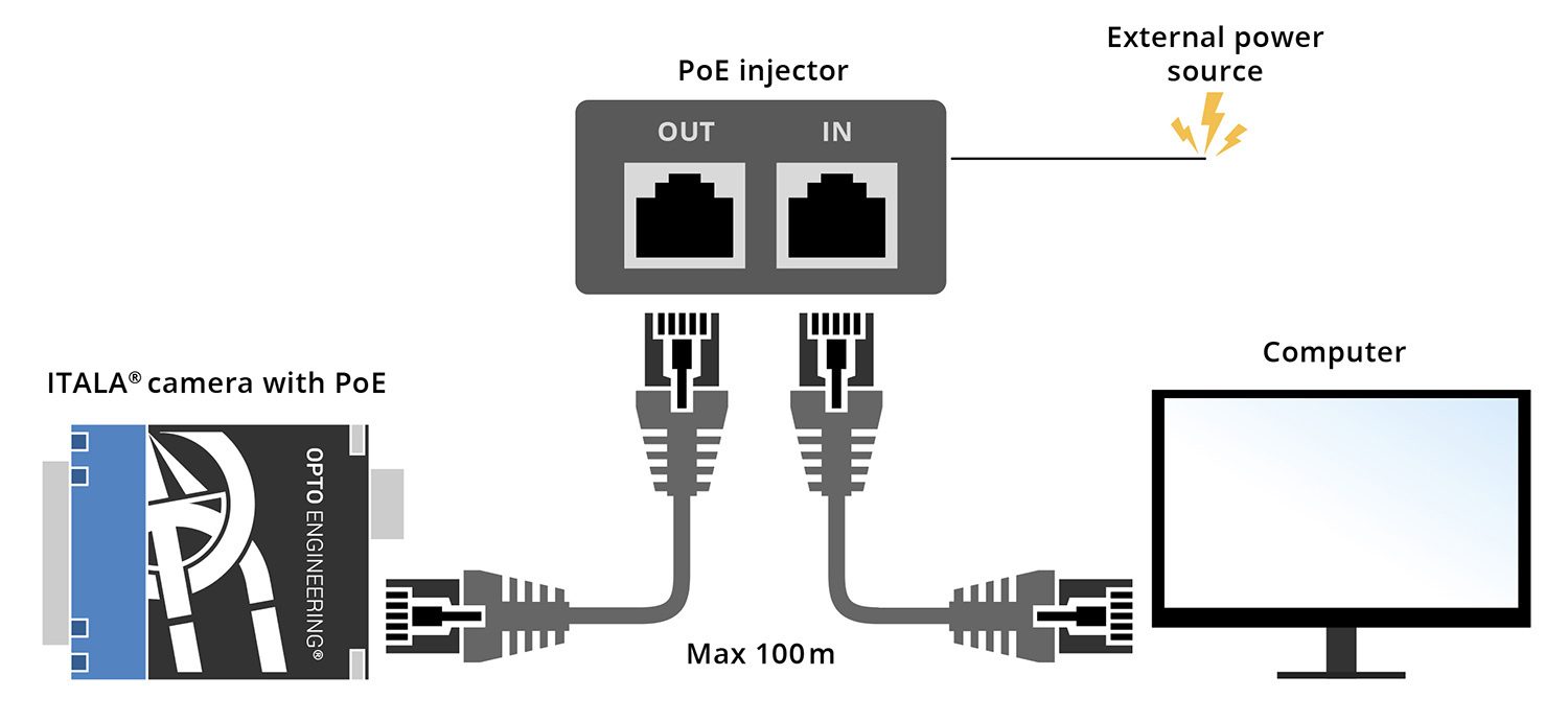
Power up the camera
Below you will find two distinct but equally viable methods for powering your camera.
POE injector
This method requires the use of one POE power injector and two ethernet cables. First, connect the POE injector to an outlet (220 [V] in Europe, 110 [V] in the US) using a power cable. Then, using two ethernet cables, connect the input of the POE injector to your PC and connect the output of the POE injector to the GigE port on the camera.
Note: you may confirm the proper connection of the ethernet cables and the POE injector by referring to the camera manual or requesting support from our Opto Engineering Technical Support Team.
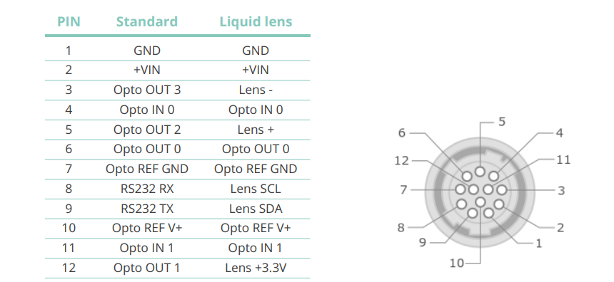
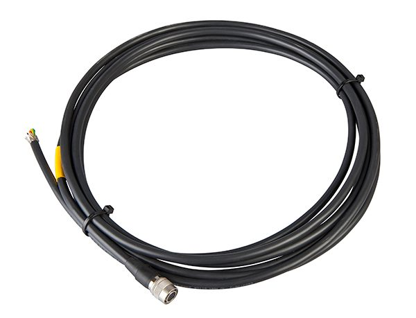
Direct Power supply of ITALA® cameras with CBGPIO001 GPIO cable
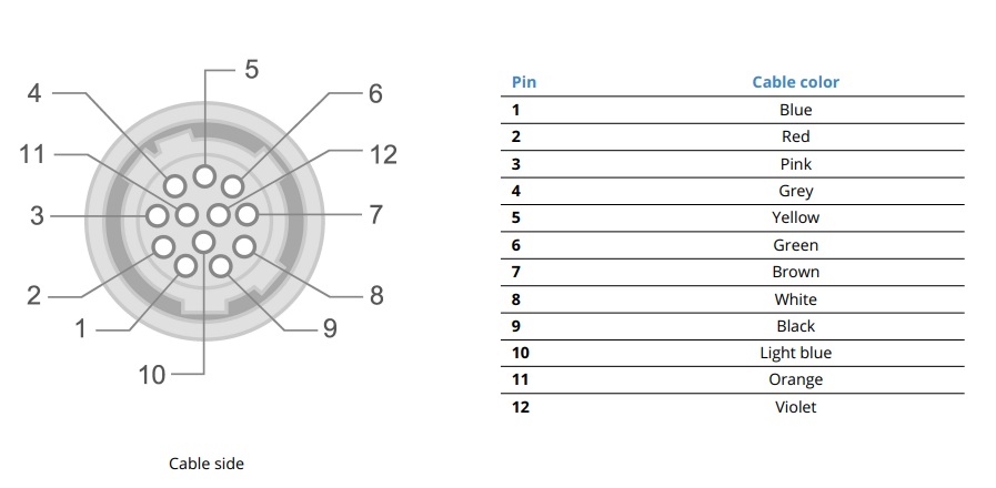
Connect the multi-purpose circular connector to the GPIO cable. To power the camera, simply connect the pin1 GND to your power supply GND, and connect the pin2 +VIN to a voltage between 12Vdc and 24Vdc.
Connecting ITALA G.EL with CBGPIO12PY6P-3M
When using the y-shaped cable (CBGPIO12PY6P-3M) be sure to first connect the camera, then the lens and finally the power supply. Never hot-swap the camera connector while the lens and/or the power supply are connected. Failing to do so may result in damaging the liquid lens integrated EEPROM.
Using this order you are ensuring that there will not be any electric discharge on the EEPROM of the liquid lens.
LED power indicator on ITALA®cameras
The camera is properly powered and ready to be connected when the LED indicator on the back of the camera is yellow.
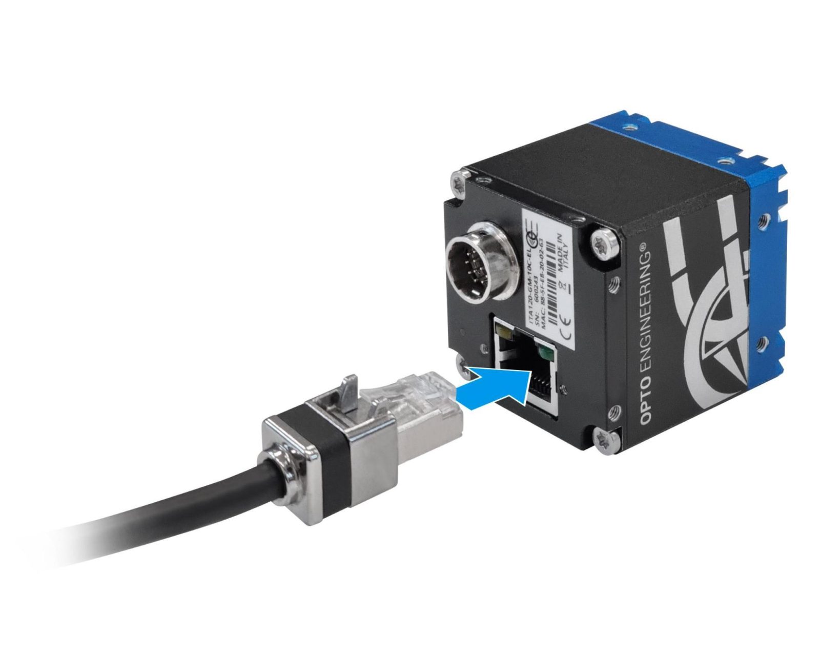
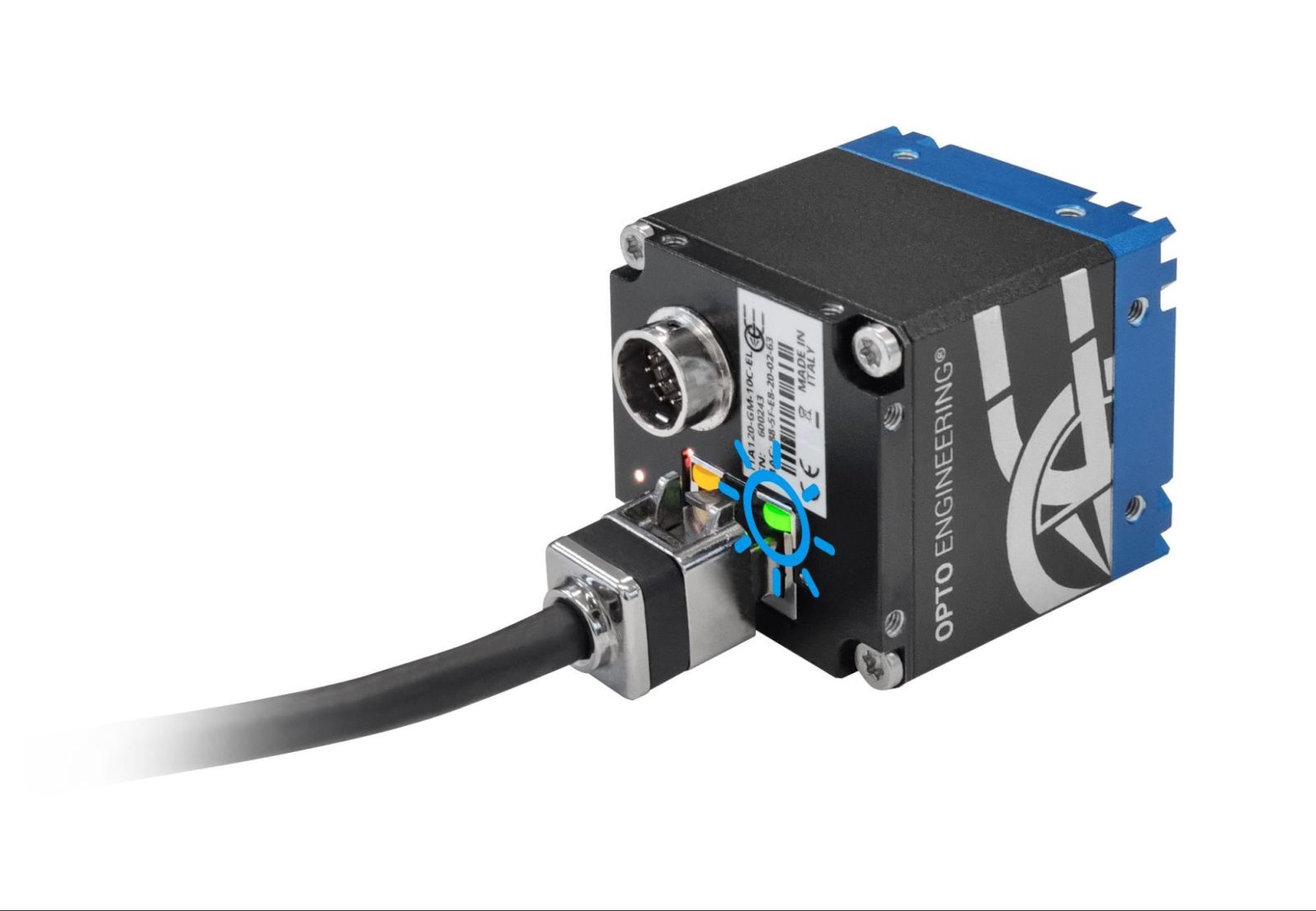
Connect ethernet cable to a network card
Connect the camera to the host device (POE injector or POE network interface card) with a suitable Cat 5e Ethernet cable or better. A shielded cable can be used to improve the system EMI immunity, especially in harsh industrial environments.
The GigE port LED will start blinking yellow once it is ready to stream.
Download and install ITALA SDK and ITALA View
ITALA® cameras come with a complete Software Development Kit, ITALA SDK, which takes full advantage of the latest standards and technologies in the machine vision industry.
The SDK includes:
- ITALA API
- ITALA View
- GenTL producer (.cti)
- Filter driver
- Documentation with code examples
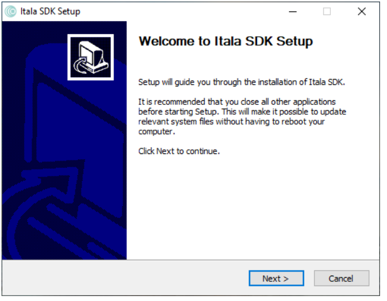
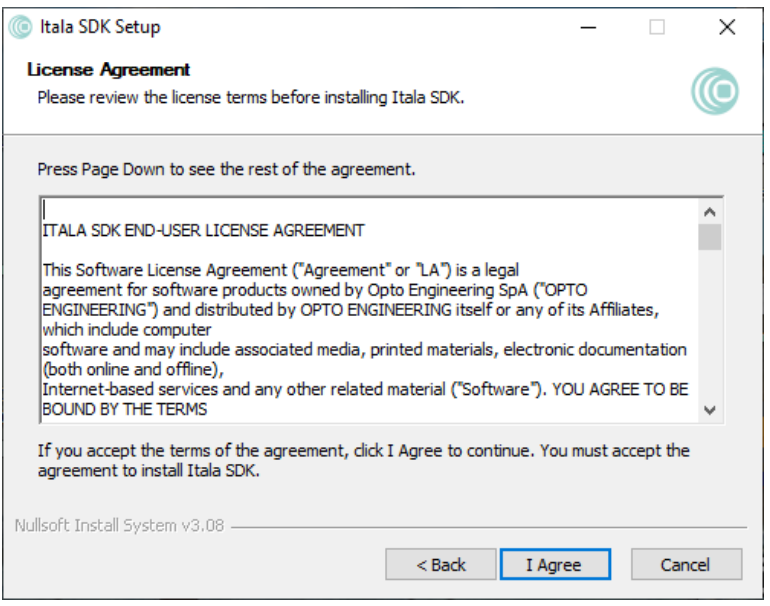
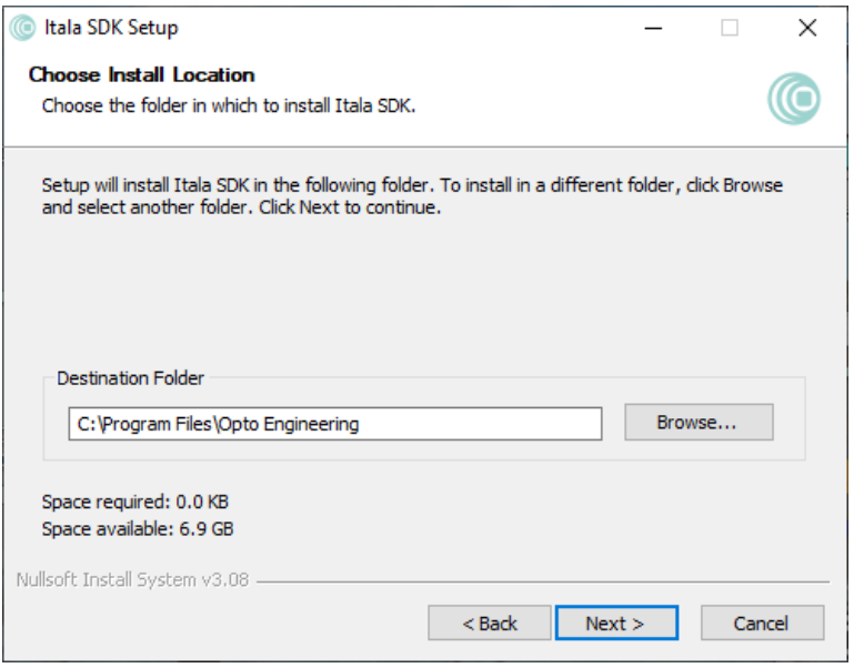
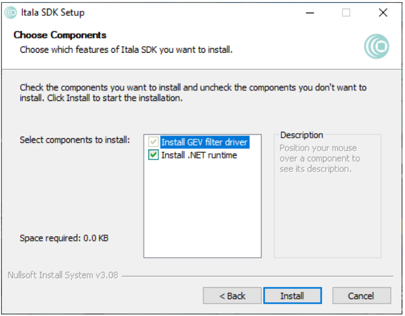
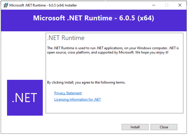
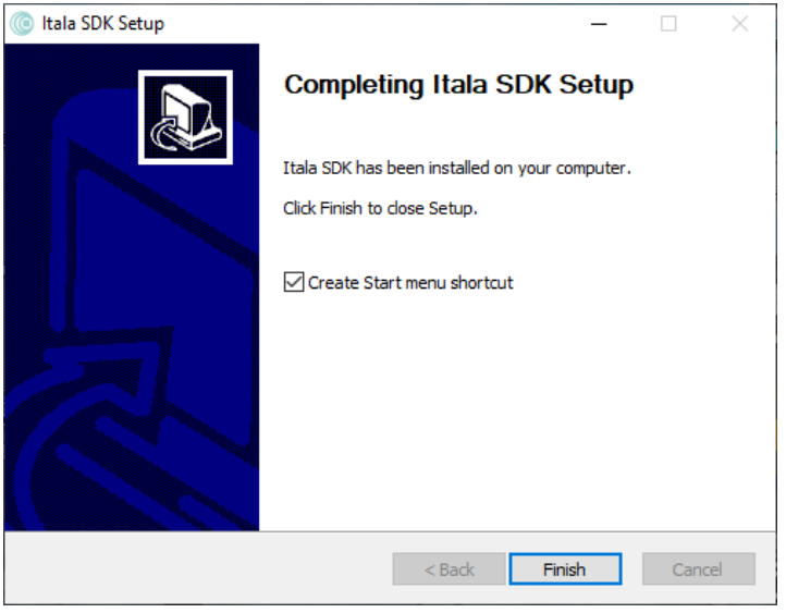
In order to install the ITALA SDK correctly, complete the following steps as indicated by the images:
- Download the ITALA SDK from Opto Engineering website here and run the installer. The ITALA SDK setup window should appear - make sure to follow the listed instructions.
- Read and agree to the license terms before installing the ITALA SDK.
- Choose the desired destination folder.
- Select the components that need to be installed. In case of installation of the filter driver only, steps 5 and 6 can be skipped.
- (Optional) In case the .NET runtime needs to be installed, click Install in the .NET runtime installation window.
- (Optional) Once the installation is complete, close the window.
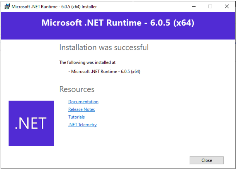
- The ITALA SDK installation will be performed automatically. The progress bar can be monitored to check the installation status. At the end of the installation, a confirmation window will be displayed.
You are now ready to integrate the ITALA® camera into your system. The ITALA API makes it easy to integrate ITALA® devices in custom applications, thanks to an extensive set of examples and complete documentation.
IP settings
The camera is factory configured to automatically obtain an IP address in DHCP/LLA mode. For the first connection, it is recommended to configure your network settings in order to use DHCP. This can be done through the following procedure:
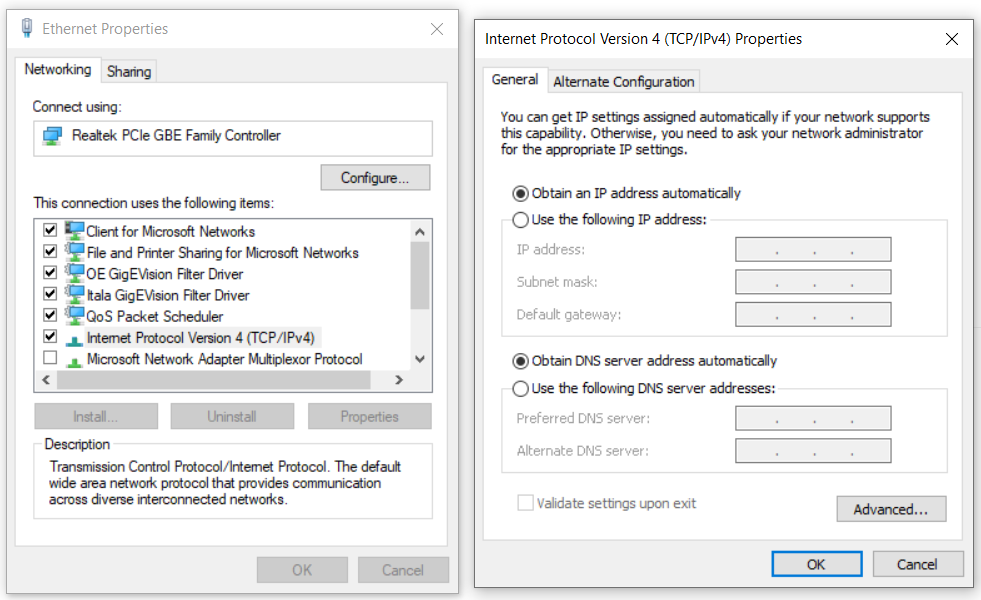
Control Panel > Network and Sharing Center > Change adapter settings, right-click on your Ethernet connection and select Properties. In the Networking tab select Internet Protocol Version 4 (TCP/IPv4) from the list and then click Properties. Select Obtain an IP address automatically and click OK. Finally, click OK on the previous window.
We recommend selecting the settings that enable your PC to assign the IP address and DNS server address automatically for the first connection. Alternatively, if you want to set a fixed IP and DNS, be sure to set the subnet mask of the camera to be the same subnet mask of your PC and to assign an IP address available in the network.
After the first connection, it is recommended to set a static IP address for both the NIC and the device whenever possible. This ensures a faster discovery process and IP negotiation.
It is recommended that the connection is as simple as possible. To achieve the best performance use a direct connection with the NIC or connect the camera and the host computer to the same Ethernet switch (without any other heavy traffic routed through the same switch).
When connecting multiple cameras to a single computer, it is recommended to connect all devices directly using multiple gigabit NICs. If you’re connecting the camera through an Ethernet switch, make sure it also supports jumbo frames. Keep in mind that if multiple devices are connected to the same Ethernet switch, they will share the available bandwidth.
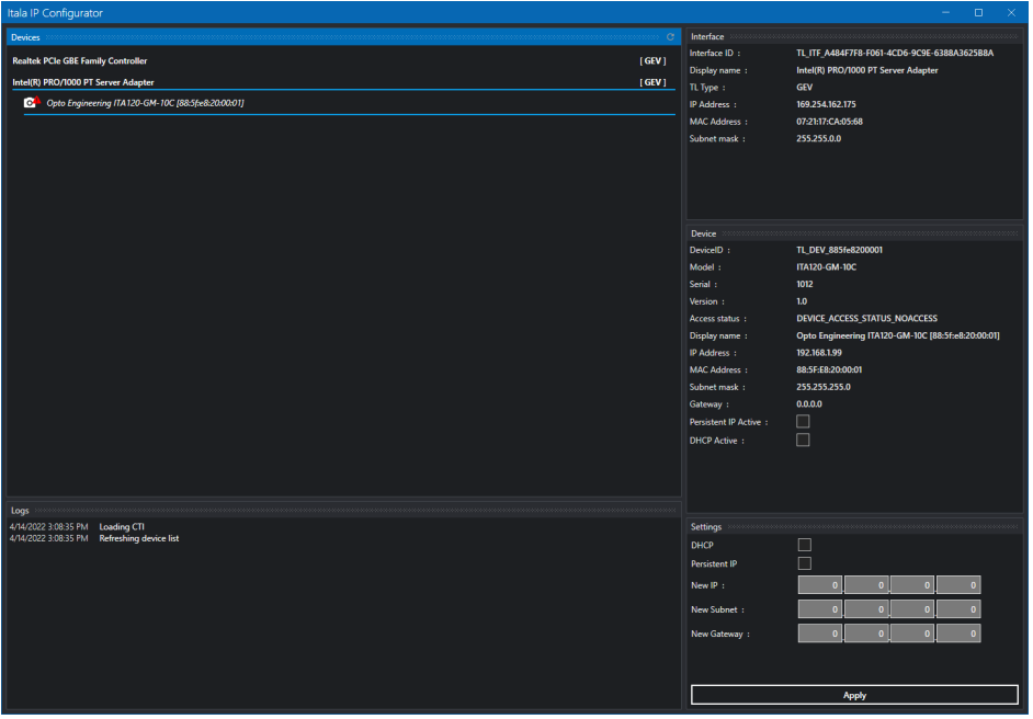
IP Configurator
From the Tools menu of Itala View, you can access the IP Configurator utility.The IP configurator has been designed to:
- Assign the camera and NIC persistent IPs but different subnets
- Assign the camera and NIC persistent IPs but different subnet masks
- Set the camera to DHCP mode and assign the NIC a persistent IP
- Assign the Camera a persistent IP and set the NIC to DHCP mode
The IP configurator presents a panel for device discovery and enumeration. On the right-hand side of the window, relevant NIC and camera information can be seen. IP configuration issues can be solved from the settings panel in the lower right corner. The camera can be forced to adopt a persistent IP by inputting the correct data and clicking the apply button. The configuration progress can be seen in the log panel. The icon next to each enumerated device shows potential issues with a red warning sign.
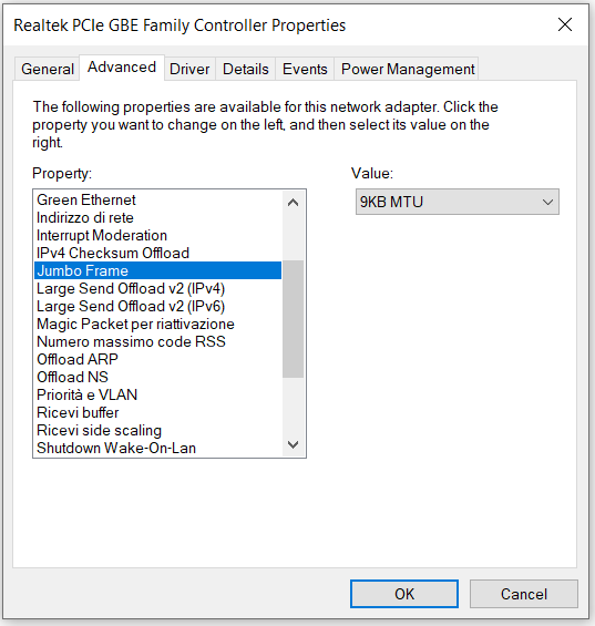
Setting the network interface card (NIC)
Inside of your camera package you shouldIn order to use ITALA® cameras it is necessary to set properly the network card interface (NIC). We suggest using Intel Pro 1000 based NIC. If you have a different Network Card Interface chip, some steps may be different or some parameters may have different names, try to follow the instructions as closely as possible.
You should access the advanced options of your network card to set it up properly. To do this go to Control Panel > Network and Sharing Center > Change Adapter Settings. Right-click on your ethernet connection and select Properties.
Here you will see a list of all the filter drivers installed on your network card, the list will include all the drivers of the camera manufacturers that you used with that network card. We suggest disabling all the drivers of other producers and keeping enabled only the ITALA GigEVision Filter Driver.
Once you have done that, click on Configure and then select the Advanced tab. Here you can see all the advanced settings of your NIC.
- Jumbo Frames can be enabled through the configuration of the network interface card (NIC) - once enabled, Jumbo frames reduce the amount of protocol overhead by increasing connection efficiency. The use of a NIC which supports Jumbo frames of at least 8192 bytes is recommended.
- Interrupt Moderation sets the possibility of the network card to be interrupted or not after it receives a packet. You want to set it to enable to obtain the best system performance.
- Receive Buffer sets the dimension of the buffer used by the driver when copying the data to the protocol memory. You need to set it to the maximum allowed value.
- Green Ethernet and Energy Efficient Ethernet are two options that will allow for less power consumption during periods of low data activity. You will want to disable both of these options to always have the best performance. Please note that cables and POE power sources are not included.
If you are still experiencing issues with your camera check if the driver of your NIC is updated to the latest version. Be aware that the latest drivers are usually found on the website of the NIC manufacturer, if you use the integrated tool in Windows it is not guaranteed to obtain the latest version of the drivers.
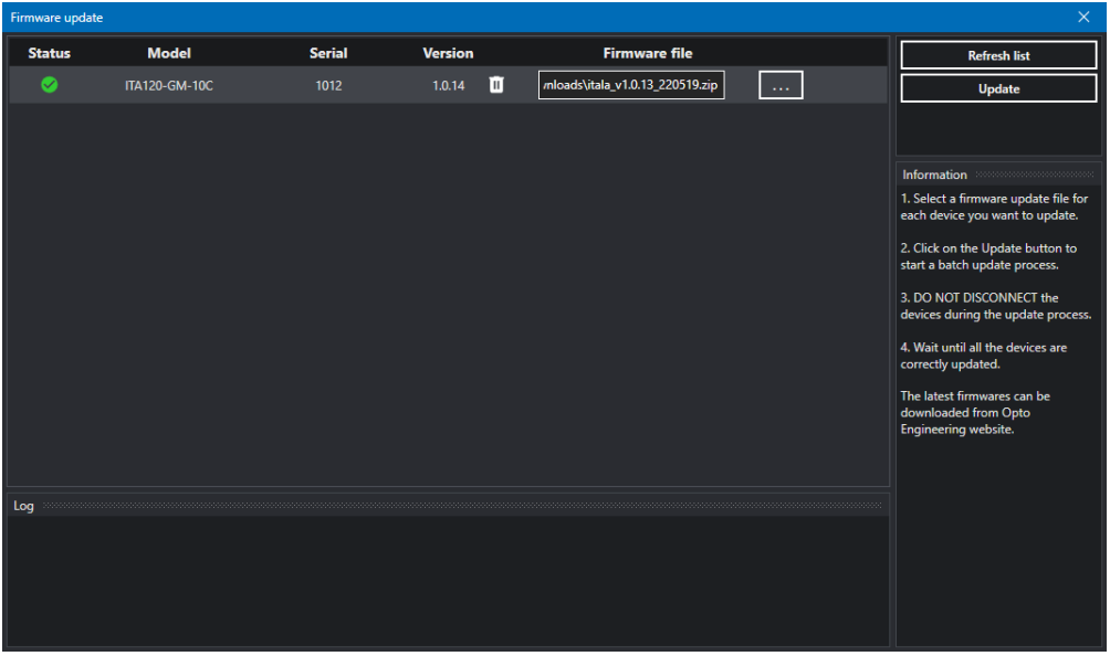
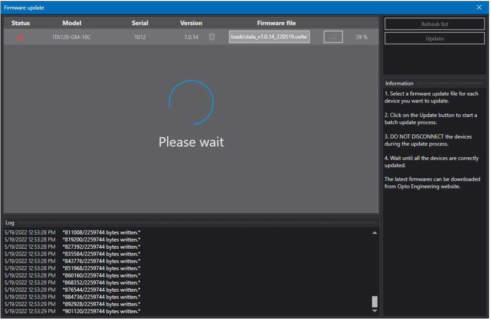
Updating the firmware
We suggest that you upgrade your camera firmware using our ITALA View GUI and the downloadable file OEFW. The ITALA View and the last firmware OEFW file can be downloaded at this link.
In order to start the update process, please connect your camera to your PC and install our ITALA SDK. Use the Tools menu in Itala View to access the Firmware Update utility. Select a firmware file for each enumerated device.
Follow these steps to update one or more devices:
- Select a firmware update file for each device you want to update.
- Click on the Update button to start a batch update process.
- Do not disconnect or power down the devices during the update process.
- Wait until all the devices are correctly updated.