
核心优势
- 预装设置
只需装上相机,即可轻松用于测量。 - 优异的光学性能
平台可提供精准可靠的测量精度。 - 经过测试的系统
该平台作为整体系统经过严格质量测试。 - 标有测得光学参数的详细测试报告
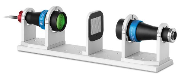
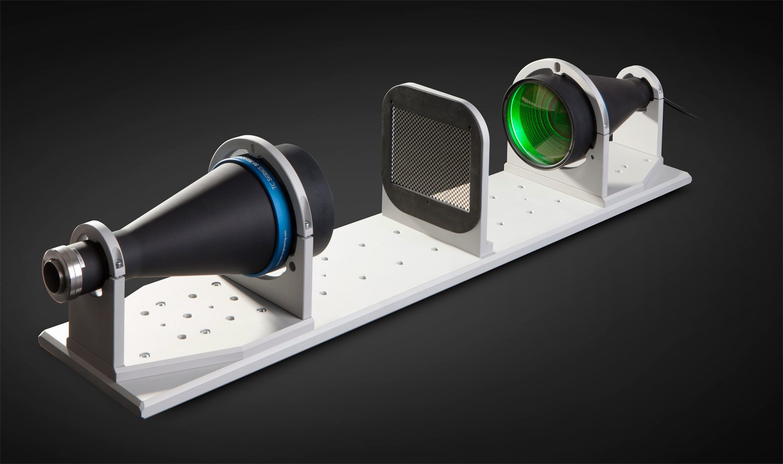
TCBENCH 系列是为便于精确测量而开发设计的完整光学系统。
每一个套件箱包含:
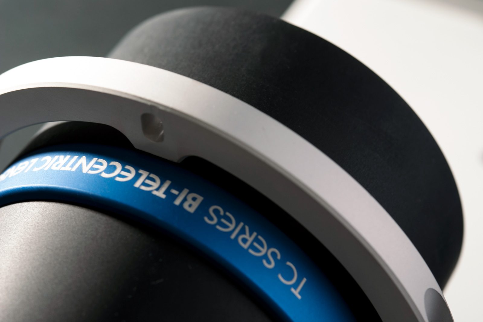
- 1 个用于 2/3" 探测器的 TC 双远心镜头
- 1 个 LTCLHP 远心照明器(绿色)
- 2 个 CMHO 机械夹
- 1 个 CMPT 底座
- 1 个 PTTC 镀铬玻璃校准图板
- 1 个 CMPT 图板支架
您知道吗?
TCBENCH 系列现在还提供新型 LTSCHP1W-GZ 绿色光源,适用于任何样品并可针对测量反射物体和具有清晰边缘的物体进行特殊定制。
主要功能
• 减少边缘衍射效应
• 增强照明均匀性,尤其是针对大视场
• 减弱对校准的敏感
订购信息
如需订购具有新款绿色 LED 模组的版本,请使用 p/n TCBENCH0xx-0-GZ(即 TCBENCH064-0-GZ)。
注释
- 工作距离:镜头最前端与物体之间的距离。 将该距离相对于标称值的偏差设定在 ± 3% 范围内可得到最佳分辨率与最小畸变。
- 工作 f 值 (wf/N):镜头作为微距镜头使用时的实际 f 值。可根据需要提供更小光圈镜头。
- 镜头内主光线的最大倾斜角度。列出了典型(平均)值和最大(保证)值。
- 实际图像相比理想化、无畸变图像的偏差率:列出了典型(平均)值和最大 (保证)值。
- 在景深的边缘,其图像依然能用于测量。 但为了获得锐度更佳的图像,应考虑采用标称景深的一半。用于计算的像素尺寸为 3.45 μm。
- 物方视场,使用 λ= 520 nm 的 Rayleigh (瑞利判据) 准则计算
- 在最大正向电流下。正向电压测量公差为± 0.06V。
- 在连续(非脉冲)模式下使用。
- 在脉冲宽度<= 10 ms、占空比<= 10%的条件下。必须绕过内置电路板(请参见技术信息)。
- 从镜头的相机法兰到光源的电子端测量。 电缆、连接器和安装螺纹不包括在内。
Features
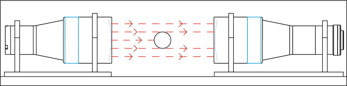
为了保证远心测量系统能达到最高的精度,试验台套件都进行了预先安装和预先校准。 远心平行光源的预安装是为了更好的优化光源的均匀性和相关的光学参数(畸变、远心度、分辨率)。 Opto Engineering®对每一套远心光学试验台的光学性能进行测试,并提供单独的测试报告用以验证整套系统测量精度。
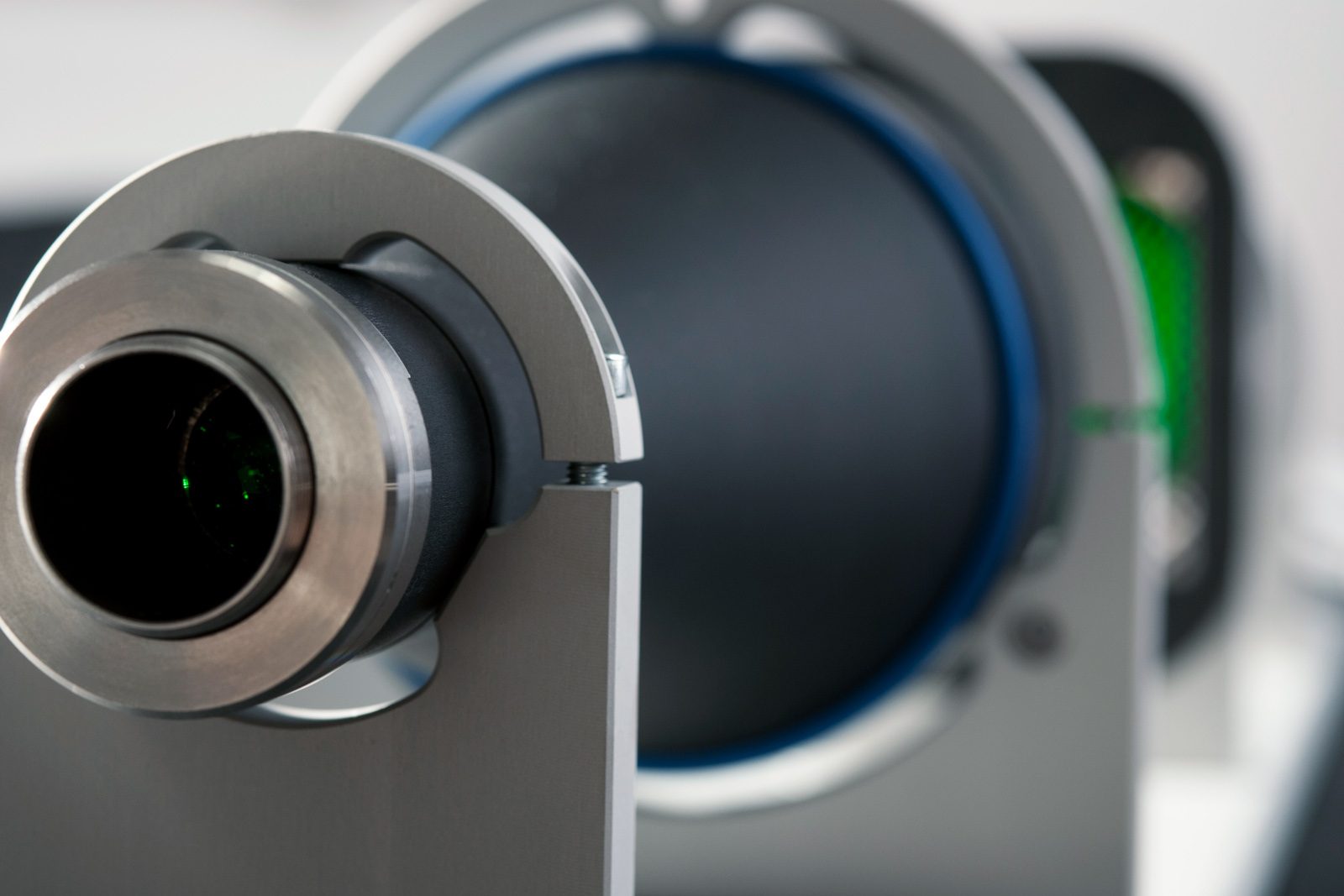
LTCL光源与远心镜头的搭配能够增加镜头的自然景深。尤其在使用兼容2/3"探测器的远心镜头时,其受光角会远大于平行光源的扩张角。
因此,这些试验台达到了无以伦比的图像分辨率和景深。远心光学试验台套件也得益于特殊的价格政策。既有高端的光学性能,又有高性价比。

Instructions for use
Operation options
LTSCHP LED modules can be operated in two ways:
- standard usage option: through the built-in electronics
- direct LED control usage option
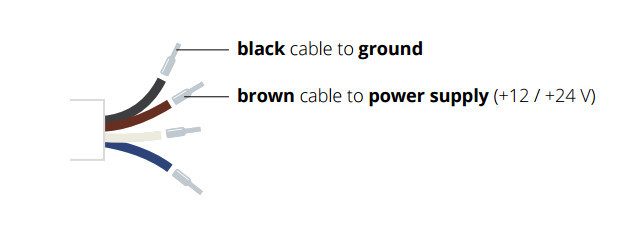
STANDARD usage option (LED control throuh built-in electronics)
Only conitinuous mode (constant voltage) is allowed.
Connection:
Connect the black and the brown cables to your +12 / +24 V power supply.
Light intensity adjustment
The built-in multi-turn trimmer allows to control the light (LED forward current) intensity with a very high degree of precision: you can bring the current intensity from minimum to maximum with 21 full turns of the adjustment screw. Simply remove the protective cap and rotate counter-clockwise the adjustment screw to increase light intensity and vice versa.

LED replacements
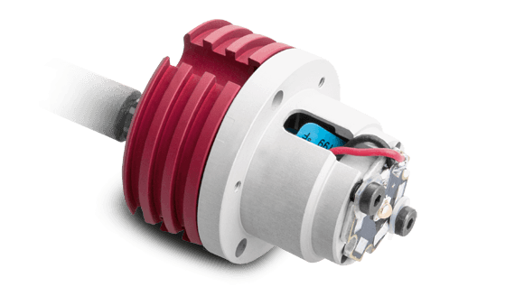
Direct LED control usage option
Both continuous and pulsed mode are allowed; the built-in electronics can be bypassed in order to drive the LED directly for use in continuous or pulsed mode. When bypassed, builtin electronics behaves as an open circuit allowing direct control of the LED source. Please note that in such case light intensity adjustment is not possible though the built-in multi-turn trimmer.
Connection:
Connect the black and blue cables as shown below (remove the LED anode protective cover).
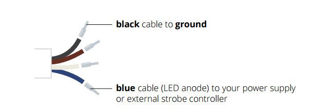
Make sure not to exceed LEDs maximum rates to avoid electrical shorts.
视频库