概述
型号
下载
技术信息
相关的
资源

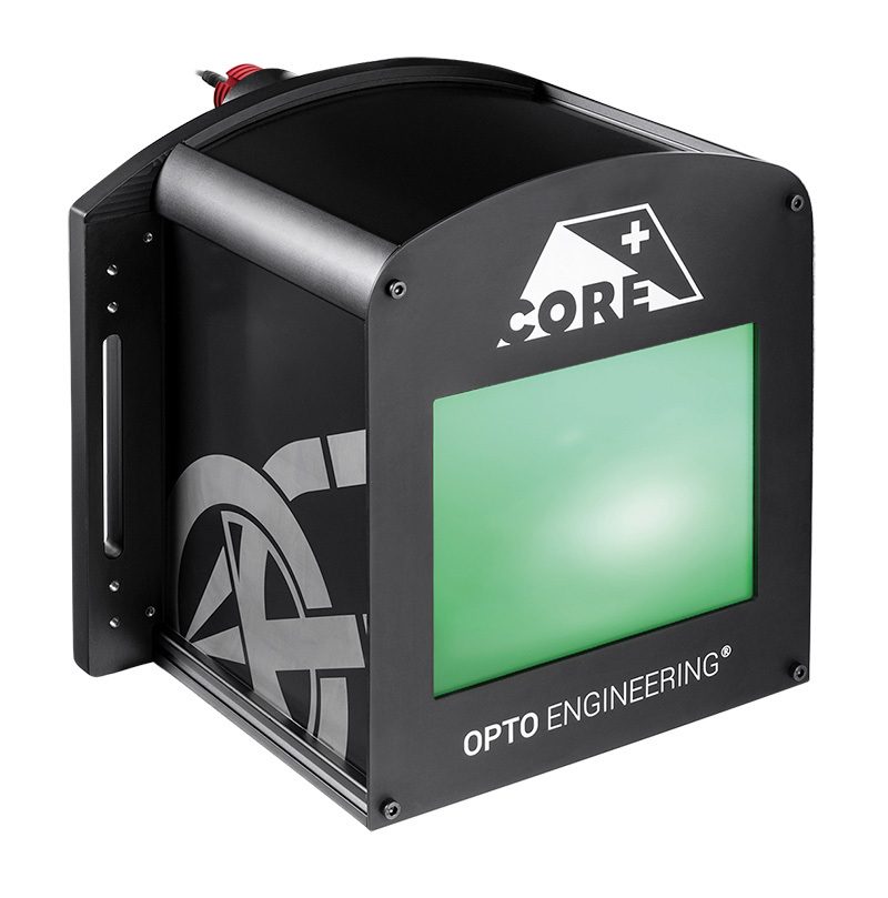
Telecentric light
准直聚焦
核心优势
- 在超紧凑结构中实现较大照明面积
LTCLHP CORE PLUS 体积小巧,其长度与市面上其他远心光源相比可缩短 45%。 - 缩小您的视觉系统尺寸
LTCLHP CORE PLUS 远心照明器的工作距离经过优化。 - 提升您测量系统的性能
可以使用 LTCLHP CORE PLUS 照明器来代替平面背光源,以提升系统的性能。 - 智能济的集成方
LTCLHP CORE PLUS 照明器集成了安装法兰,无需额外的夹具即可轻松安装。 - 系统的紧凑性堪称一大竞争优势
小型的视觉系统或测量机器已成为业内首选。
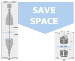
LTCLHP CORE PLUS 远心照明器经过专门设计,可在较小空间内实现大面积照明。该产品的长度与市面上其他远心光源相比可缩短 45%。
远心镜头的长度和工作距离会在很大程度上决定视觉系统的尺寸。此类产品的工作距离范围经过优化,使得测量系统的尺寸尽可能紧凑,从而使系统的整体尺寸缩减了一半之多。
得益于超紧凑的结构,您可在传统远心光源不适用的位置轻松集成 CORE PLUS 准直照明,以代替普通的漫射型背光源,从而提高系统性能。
LTCLHP CORE PLUS 光源经过专门设计,实现了智能集成。它们采用了内置安装法兰设计,因此,无需额外的安装夹具便可实现安装。
发现更多
优势
节省更多
• 所用材料更少,制造成本更低• 无需其他夹具固定,从而缩减了安装成本
• 所需存储和使用空间更小
• 尺寸更小,运输费用更低
• 运输风险更低
销量更高
• 系统体积更小,从而推动销售额提升
实际应用案例及案例历史
配备“传统”远心镜头和光源的精度测量系统与 CORE PLUS 远心镜头和光源的对比。
请稍等
无法处理您的请求
返回型号
过滤器
关闭
重置过滤器
注释
- 光束形状呈非圆形。如需了解最小光束尺寸,请参阅技术信息。
- Opto Engineering®推荐在高精度测量应用中使用绿光。
- 公差± 10%。
- 在最大正向电流下。正向电压测量公差为± 0.06V。
- 在连续(非脉冲)模式下使用。
- 在脉冲宽度<= 10 ms、占空比<= 10%的条件下。必须绕过内置电路板(请参见技术信息)。
- 夹紧法兰的最大尺寸。
- 标称数值,无垫片。
返回型号
参数
TC CORE PLUS telecentric lens.
Setup instructions 1
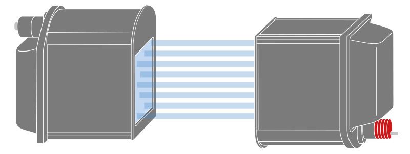
To build a telecentric measurement setup it’s necessary to position a LTCLHP CORE telecentric illuminator upside down with respect to the TC CORE PLUS telecentric lens.
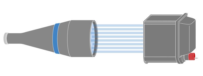
LTCLHP CORE PLUS telecentric illuminator
Setup instructions 2
LTCLHP CORE PLUS telecentric illuminator is also a perfect solution when coupled with classic telecentric lenses (e.g. TC series).
Application cases
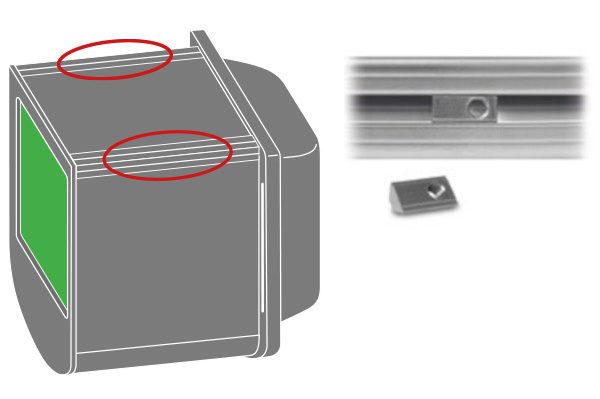
Integrated extruded aluminum profiles with M5 T-slot nuts allow for easy and cost-effective mounting.
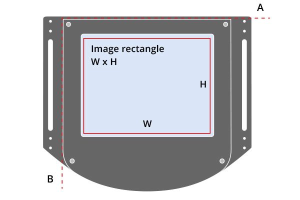
The width of the beam rectangle is aligned along the A axis. The height of the beam rectangle is aligned along the B axis.
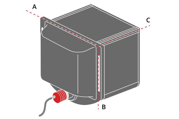
A, B an C indicate the mechanical dimensions of the illuminator.
视频库

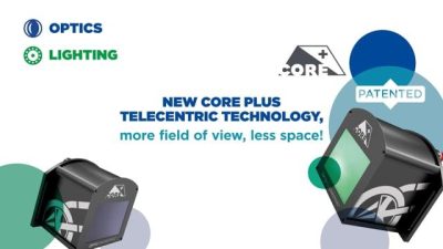
CORE Plus Technology