Interfacing OEVIS® with third-party automation devices
Using Adam I/O modules
Using Advantech PC Digital IO
Using Hilscher cards
Using Modbus with Siemens PLC
Using Adam I/O modules
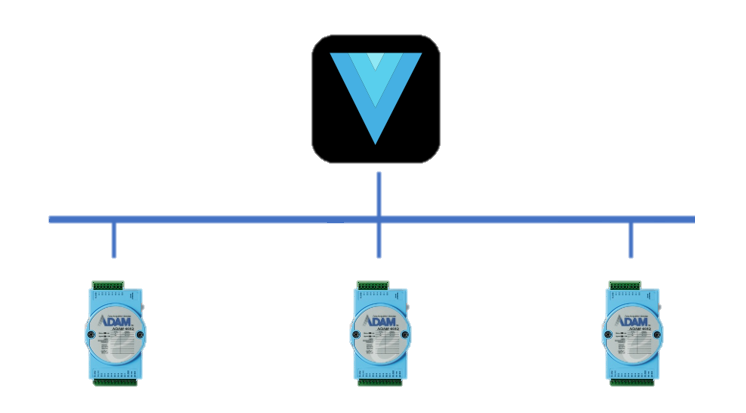
ADAM-6000 series Ethernet-based data acquisition and control modules provide I/O, data acquisition, and networking capabilities in one module, allowing you to build a cost-effective distributed monitoring and control solution for a wide variety of applications. Through a standard Ethernet network, ADAM-6000 modules can retrieve I/O values from sensors and can publish them as real-time I/O values to networking nodes. With OEVIS®, ADAM-6000 modules allow you to build up a cost-effective system for e-manufacturing applications. This guide is for model 6052, which is currently integrated.
System setup
For specifications, electrical connections and IP address setup, we recommend reading the user manual in advantech webiste:
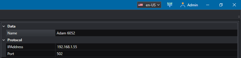
From the System/Device tab, add Adam 6052 as new device
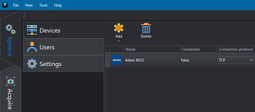
and enter the IP address of the device.
Example of data reading from inputs
From Job tab select Communication / IO / Advantech / Adam6052_ReadInput.
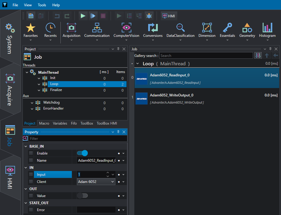
Select from IN / Input the port to be read, between 0 and 7. After running the program, you will find the input status in OUT / Value.
Example of data writing to outputs
From Job tab select Communication / IO / Advantech / Adam6052_WriteOutput.
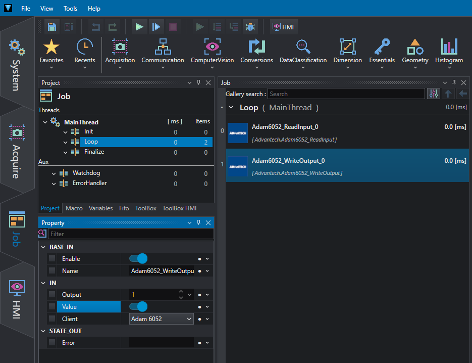
Select from IN / Output the port to be activated, between 0 and 7. Select the state in IN / Value and run the program.
Using Advantech PC Digital IO
OEVIS® can be used to read and write to the I/O interface of some industrial PCs distributed by Advantech. This guide refers to the model UNO-148 Industrial PC.
For technical details on how to connect inputs and outputs to external devices, please refer to the product user manual.
Example of how to read from inputs
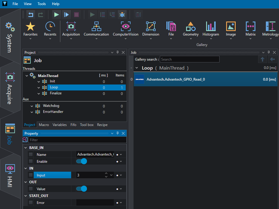
There are 8 x digital inputs configured from GPIO pins for status reading.
To read an input select the GPIO_Read tool from Communication/Advantech and set the bit to read to IN/Input (0 to 7), for the example in figure 1 we read the fourth bit.
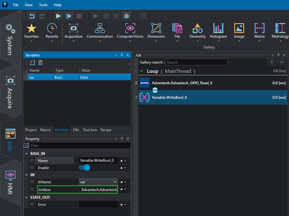
The state of the input bit can be passed as true/false value to the next tool, as in Figure 2, we write it into a boolean variable, connecting the GPIO_Read tool in IN/InValue and the name of the variable in IN/InName.
Example of how to write to outputs
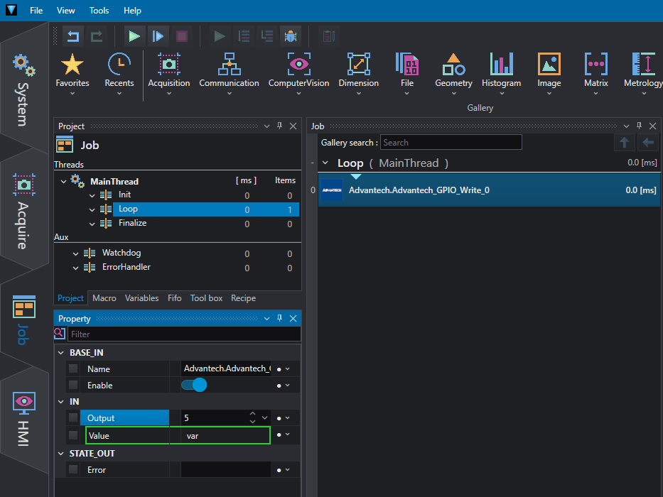
There are 8 x digital outputs configured from GPIO pins for on/off triggering.
To write an output select the GPIO_Write tool from Communication/Advantech and set the bit to write to IN/Output (8 to 15) and a boolean variable whose true or false state will be written to the output. In the example in figure 3 we write the sixth bit with the value of the variable var.
Using Hilscher cards
For over 35 years the name Hilscher has stood for trendsetting automation solutions. Since its founding, has grown to one of the world's leading suppliers of industrial communications solutions, including 13 subsidiaries in 11 countries, comprised of more than 400 employees.
OEVIS® can be used both as a client and as a Modbus server to read or write the registers of a Hilscher card set as Modbus server or client.
Example of integration between Hilscher Card as Modbus server and OEVIS®
In this tech notes we will refer to the model card CIFX 50E-RE. For technical details you can see here:
Here you can find the user manual, complete with installation instructions:
We recommend that you read carefully at least the part regarding the installation of hardware and software for the correct functioning of the card. In addition, to be able to function as a master, the card needs the master license. Please contact your dealer for more details.
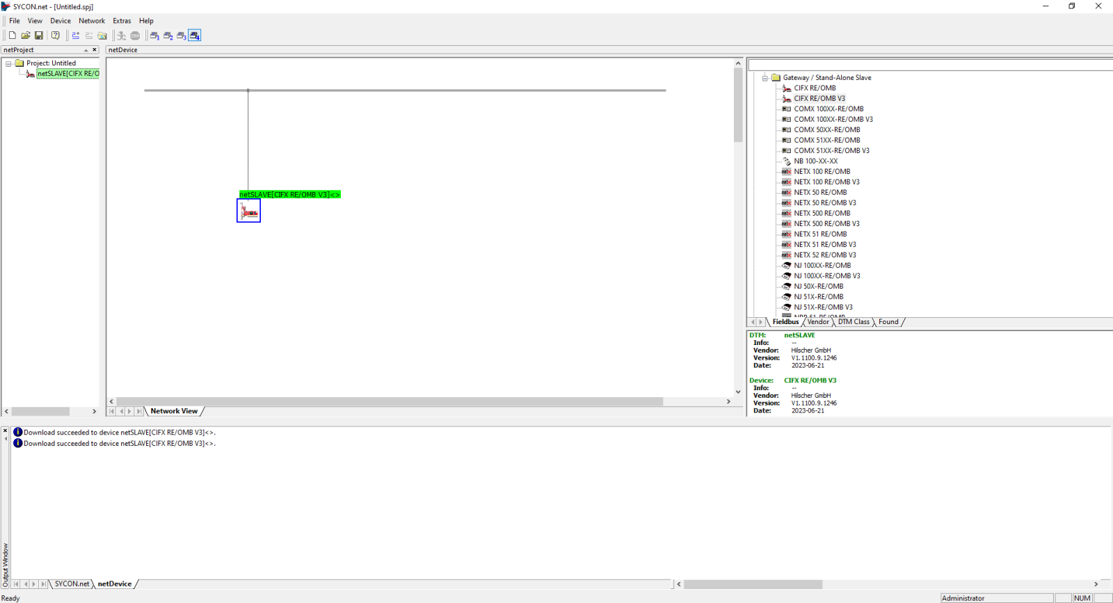
To configure the card, you must have installed the software SYCON.net.
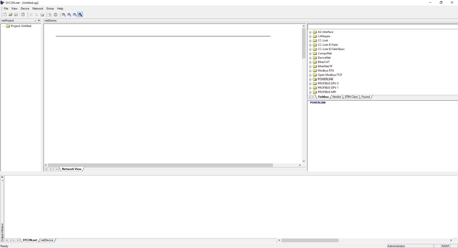
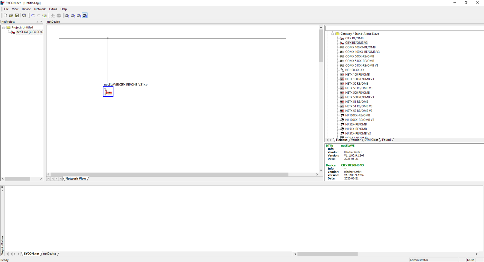
Drag CIFX RE/OMB V3 to the connection bar.
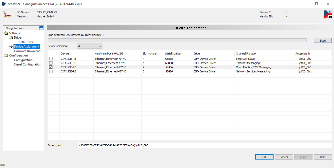
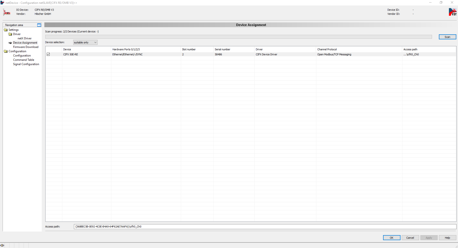
Right click and select Configuration / Device Assignment / Device selection and set to all. In this figure we see two cards installed, we will select the first channel (ch0) of the first card (cifx0).
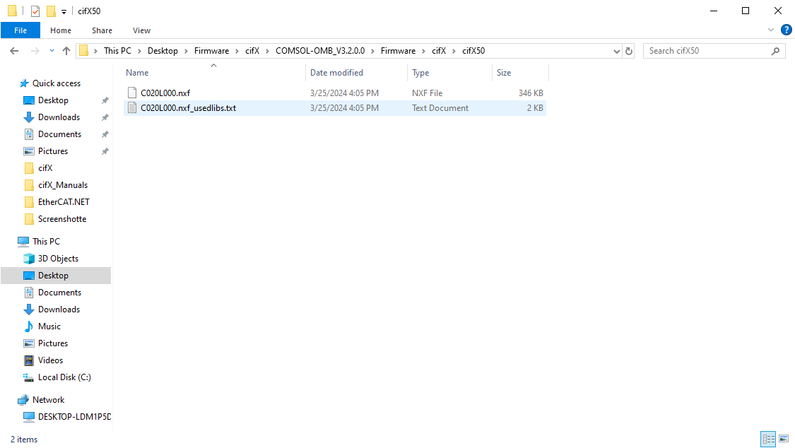
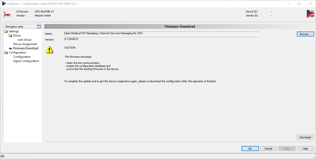
Select Firmware Download and select the firmware (.nxf file) as shown in the figure:
Load the firmware into the card with Download. It is recommended to turn off and on your PC after loading.
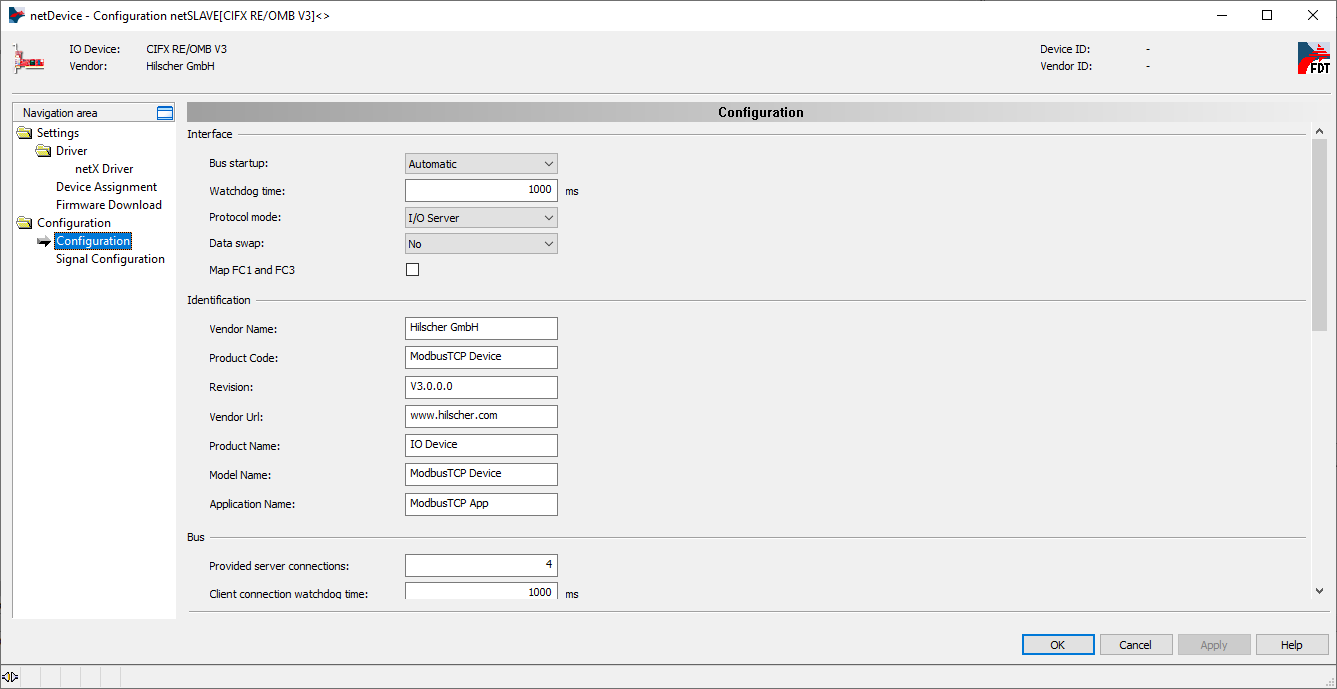
In configuration, set the Protocol mode to I/O Server,
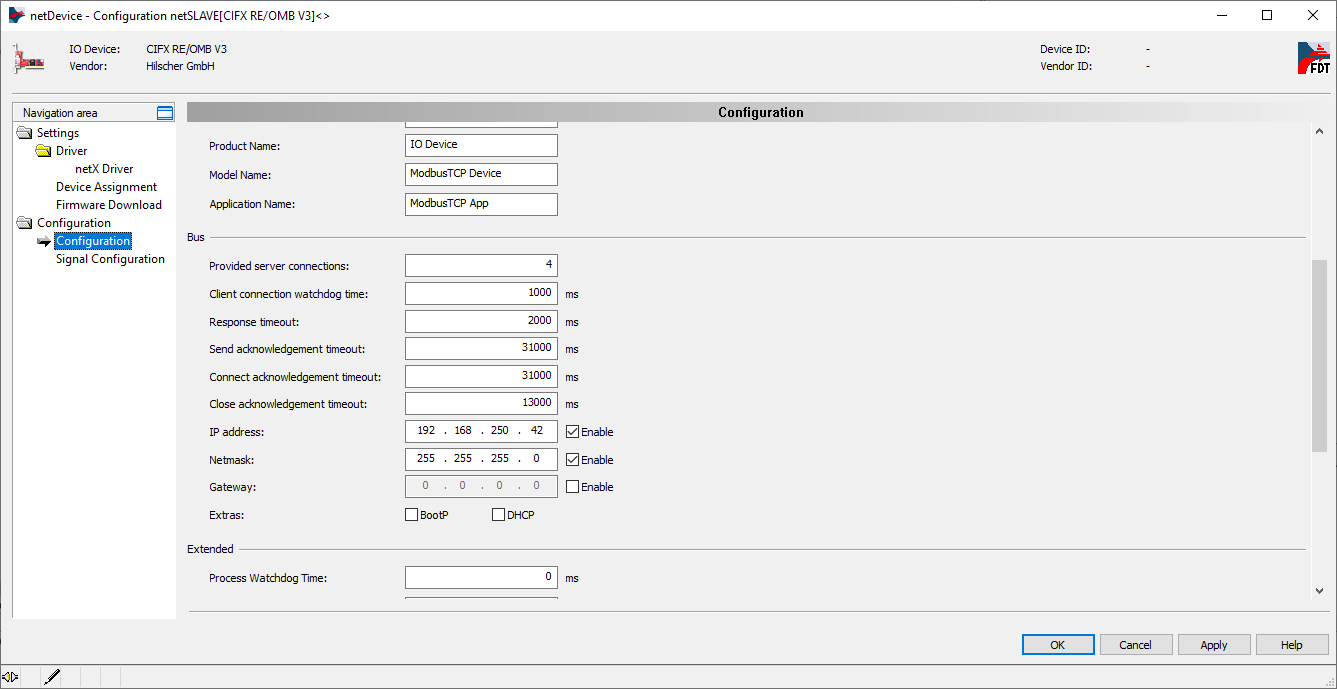
and set the IP address and netmask of the card, confirm with Apply/OK.
By selecting the card, with the right mouse button, you have to select Download to load this configuration. You can also Connect or Disconnect the card,
or select Diagnosis to view the diagnostics window.
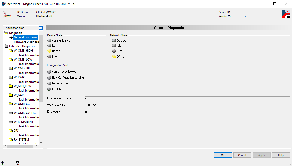
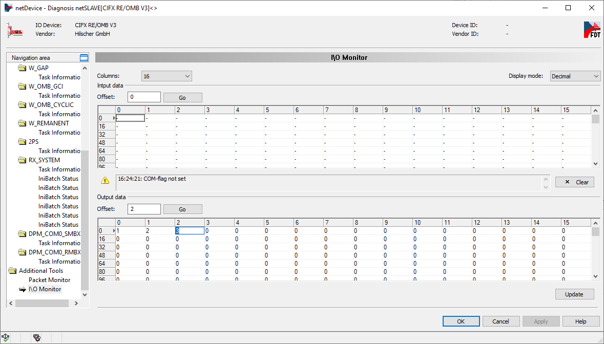
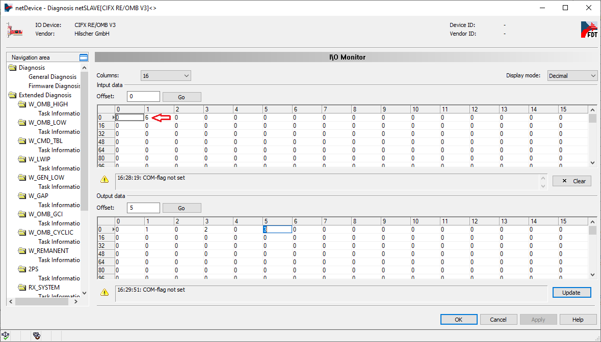
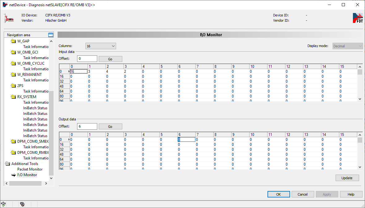
You can also find more information about diagnostics in chapter 7.10 , Open Modbus/TCP , of the user manual. In Additional Tools / I\O Monitor you can check the contents of the registers, which is useful for debugging.
There are two ways to access the registers with OEVIS®, via Modbus inspector/device or with the Hilscher device.
Modbus inspector/device
Suppose we have the values 1,2,3 (as bytes) written in the registers (16 bits) 0,1/2,3/4,5 of the card.
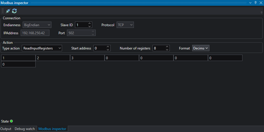
To test the operation and read these values in OEVIS® you can use the Modbus inspector (View / Show Window / Modbus Inspector).
After setting Big Endian as format and the IP Address of the card, set ReadInputRegisters as action, start address to 0, number of registers at least 3, and format for example as decimal. Press connect and then action to read the values from the card.
To write to registers set the action to WriteSingleRegister, start address to 0, and format for example as decimal and enter a value, for example 6. Press connect (if not already connected) and then action to write the values to the card.
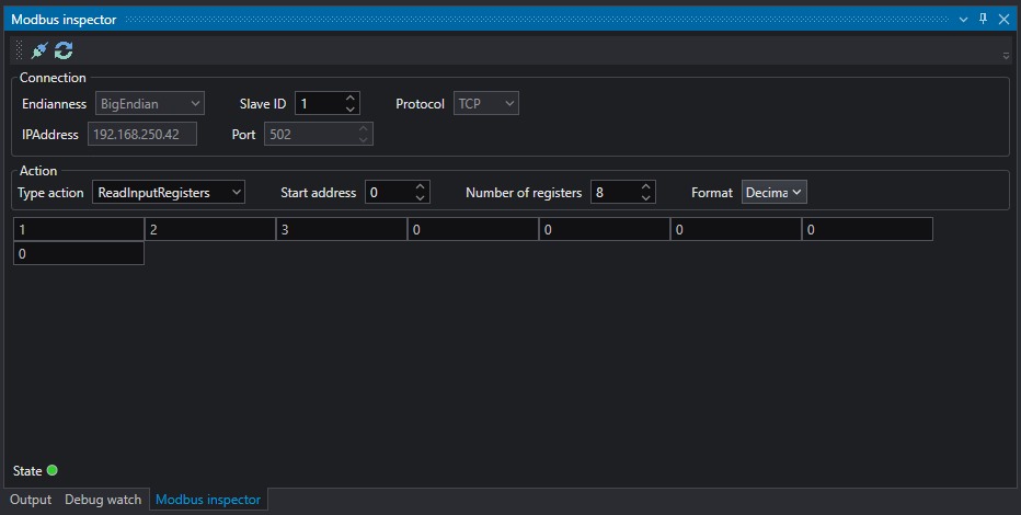
Pay attention to the format, in OEVIS® you work in registers while in SYCON.net the display is in bytes.
To use the OEVIS® Modbus device, please refer to the tech notes relating to Modbus.
Hilscher device
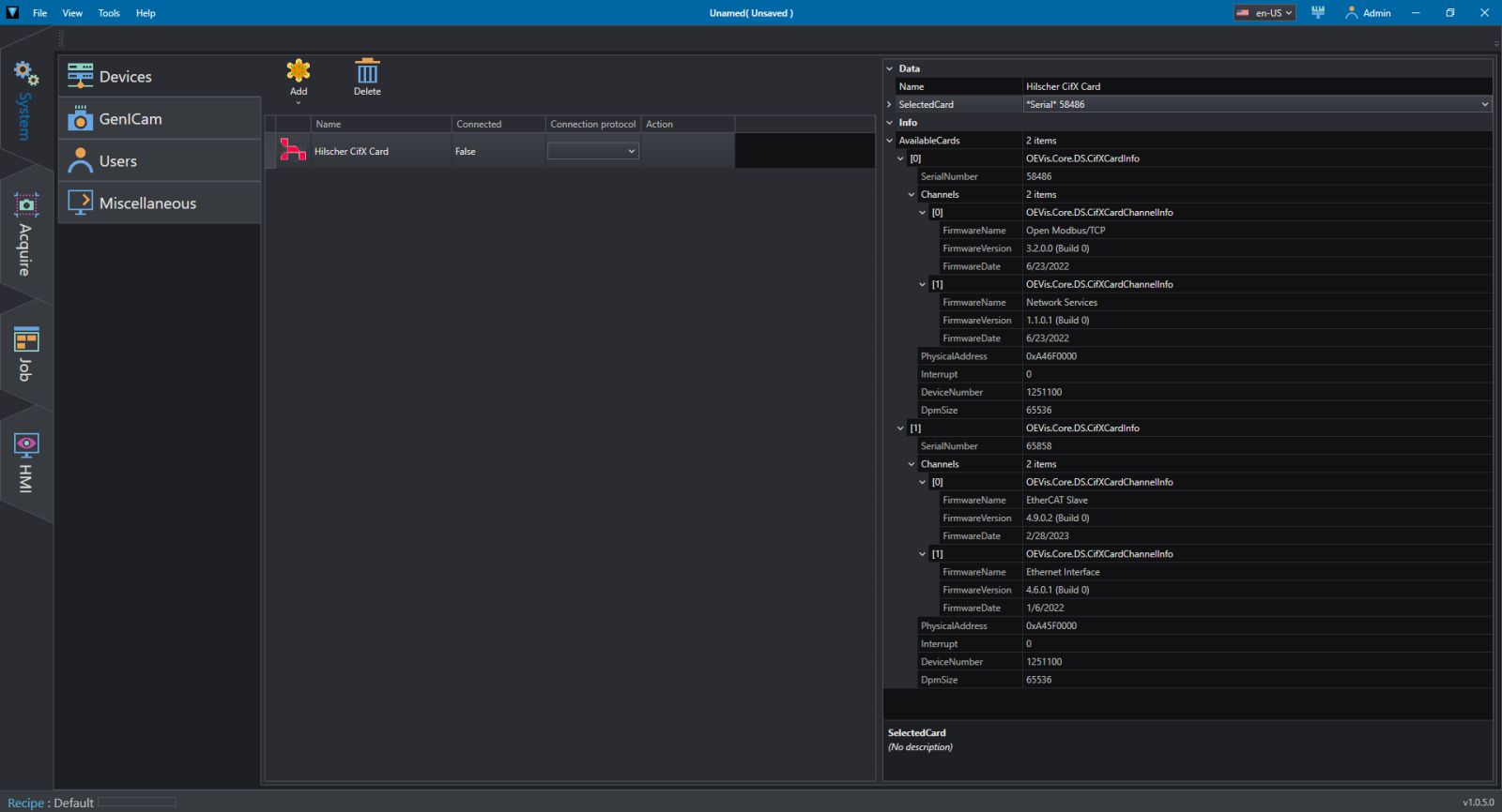
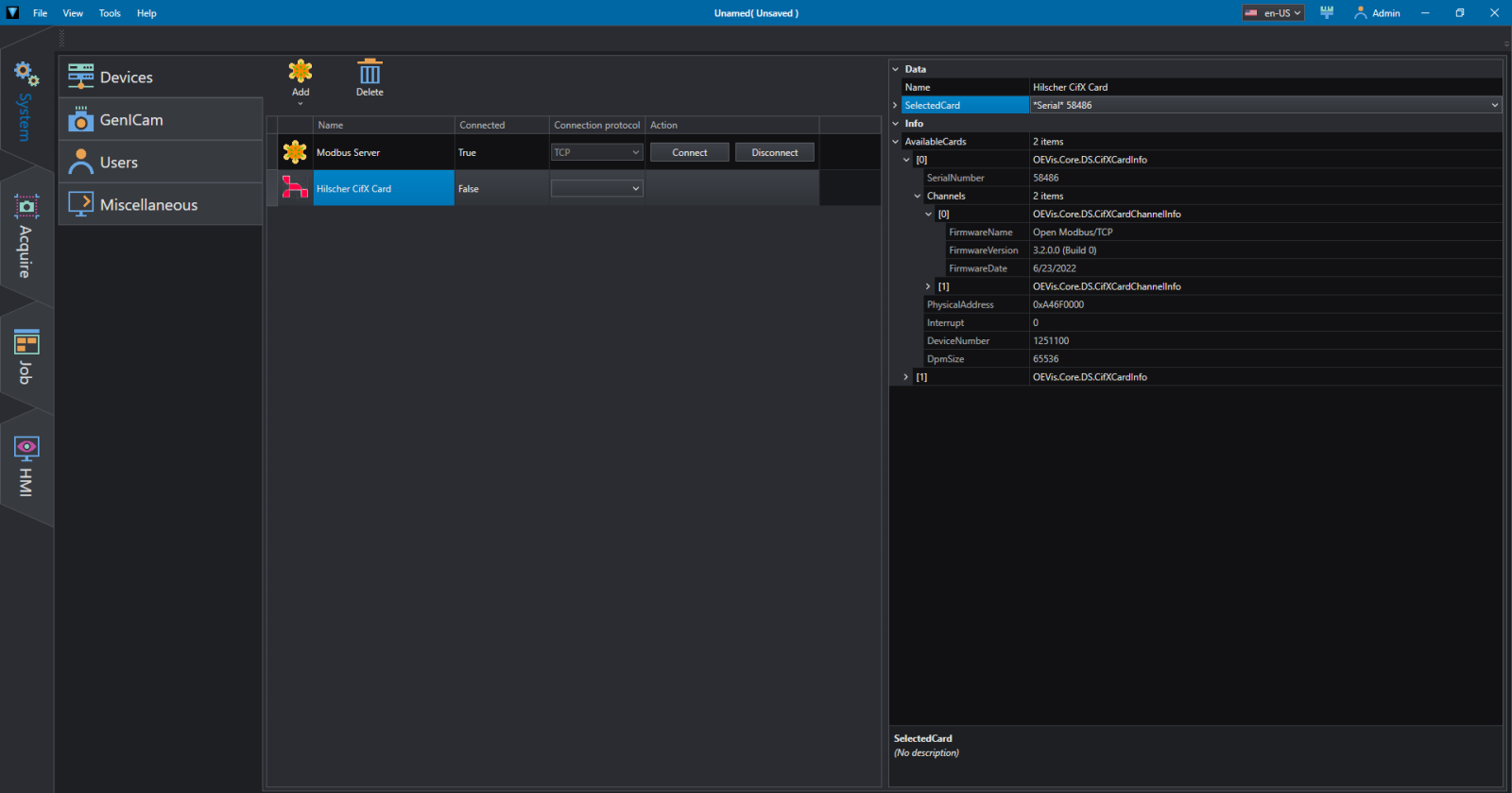
In System/Devices add a Hilscher card, selecting the serial number on the right. If this value is not known or there are more cards installed in the system you can help yourself using the Info panel.
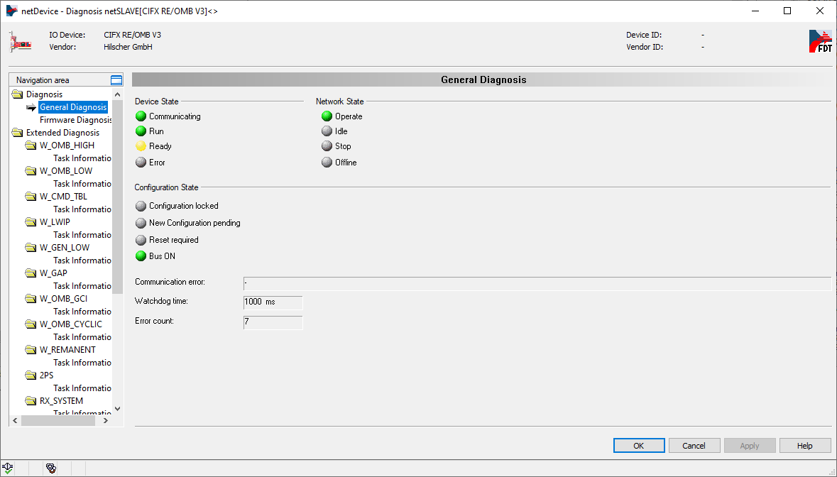
Also check that the card is in operate mode via diagnostics panel, otherwise refer to the troubleshooting section.
Let's assume we have the registers as in the situation shown in the figure below:
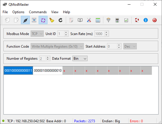
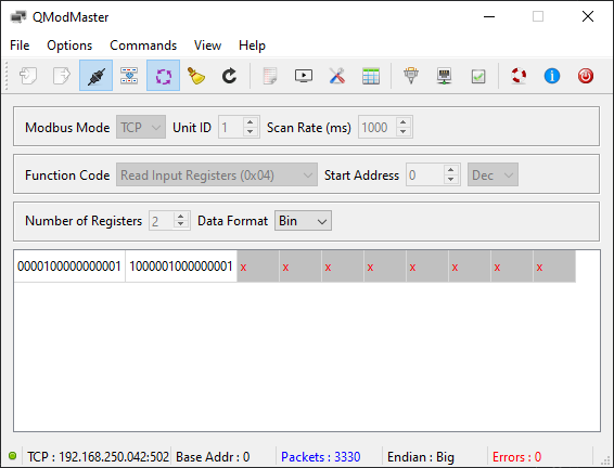
If the board does not have a client connected you can help yourself by using an application like QModMaster to simulate a connected client and read/write values as real situation.
As you can see from the image below, we used QModMaster to write the registers in the Hilscher board as in the previous figure. The registers written in QModMaster are 2, so you can see 4 bytes in SYCON.net I\O Monitor:
| Byte 0 | Byte 1 | Byte 2 | Byte 3 |
|---|---|---|---|
| 00010000 | 00000011 | 00000100 | 00000010 |
| 16 | 3 | 4 | 2 |
On the OEVIS® side, in Job/Communication insert the HilscherCifXReadInt tool, select the card loaded in devices and leave the parameters as in the figure, then give a Run Once.
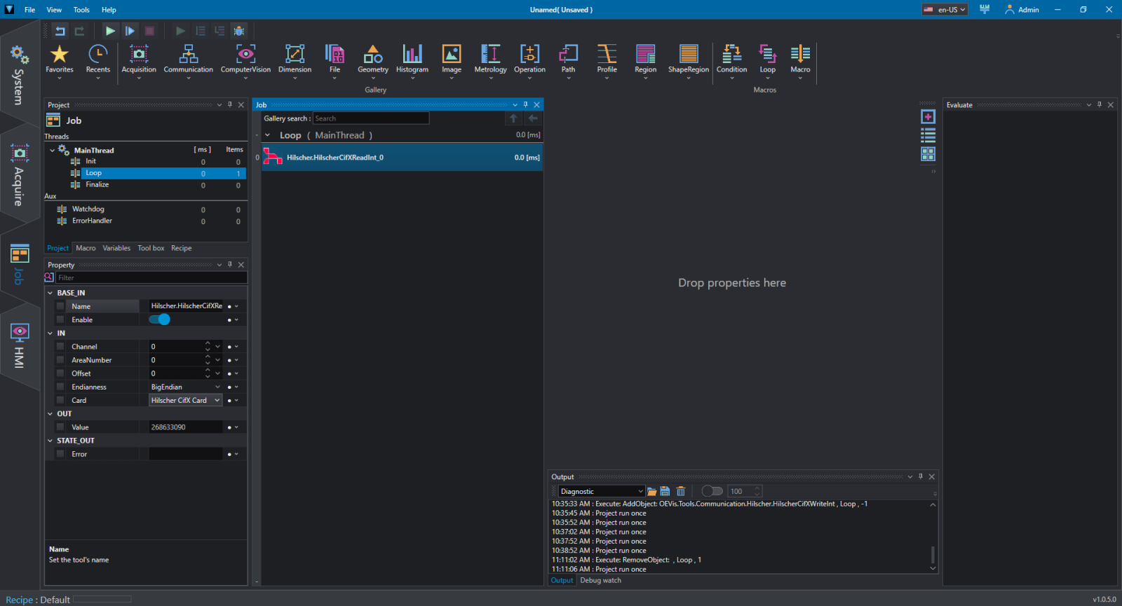
In the OUT section the read value will appear. Having read an integer (4 byte) the resulting value will be:
(16 × 2^24) + (3 × 2^16) + (4 × 2^8) + (2 × 2^0) = 268633090
This is intended to be an example of how to pay attention to conversions if you want to obtain the desired results.
To write in the registers, in Job/Communication insert the HilscherCifXWriteInt tool, select the card loaded in devices, insert a value (for example 134316545 half of the first reading) and leave the parameters as in the figure, then give a Run Once.
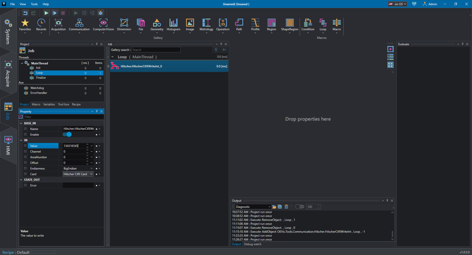
As you can see from the client the values read correspond to the bits shifted to the right by one, so exactly half the value of the first reading example (268633090/2=134316545).
Troubleshooting
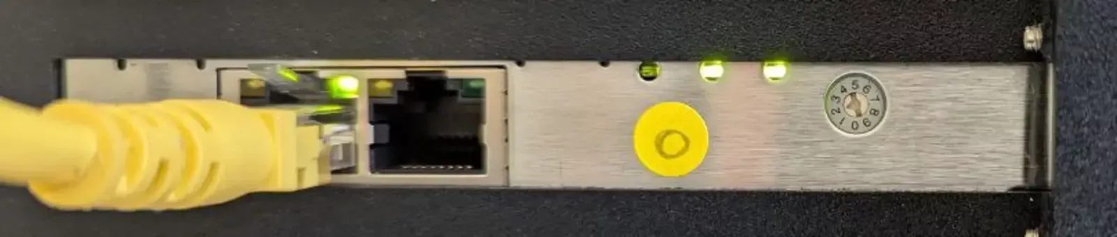
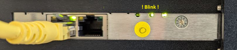
In Hilscher device mode, if there is no client connected to the board, it will not be possible to access the registers, because functions in OEVIS® cannot establish a connection. This condition can be easily verified by checking the LEDs on the board itself:
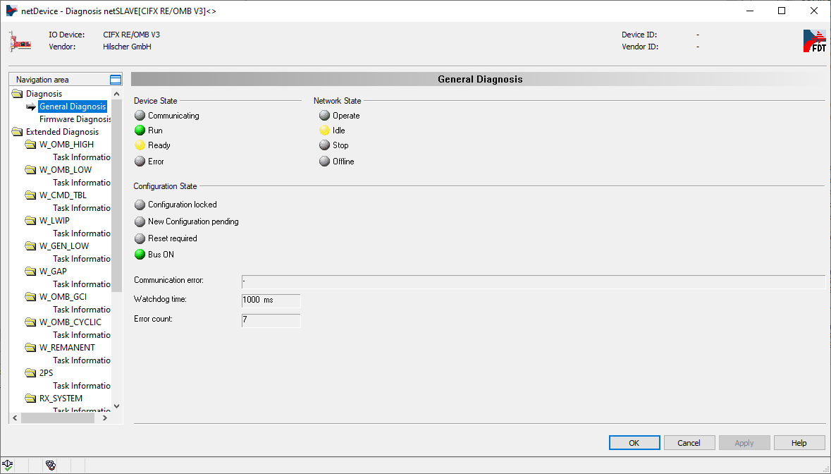
Or you can check the Operate led in diagnosis area:
If you don't have a client connected you can use a program like QModMaster to simulate its presence.
Example of integration between Hilscher Card as Modbus client and OEVIS®
For basic card setup/firmware loading and software installation on your PC, refer to the first part of this guide if you haven't already done so. However, we recommend that you read the entire first part to better understand how the system works. This time we will configure the selected card as a client:
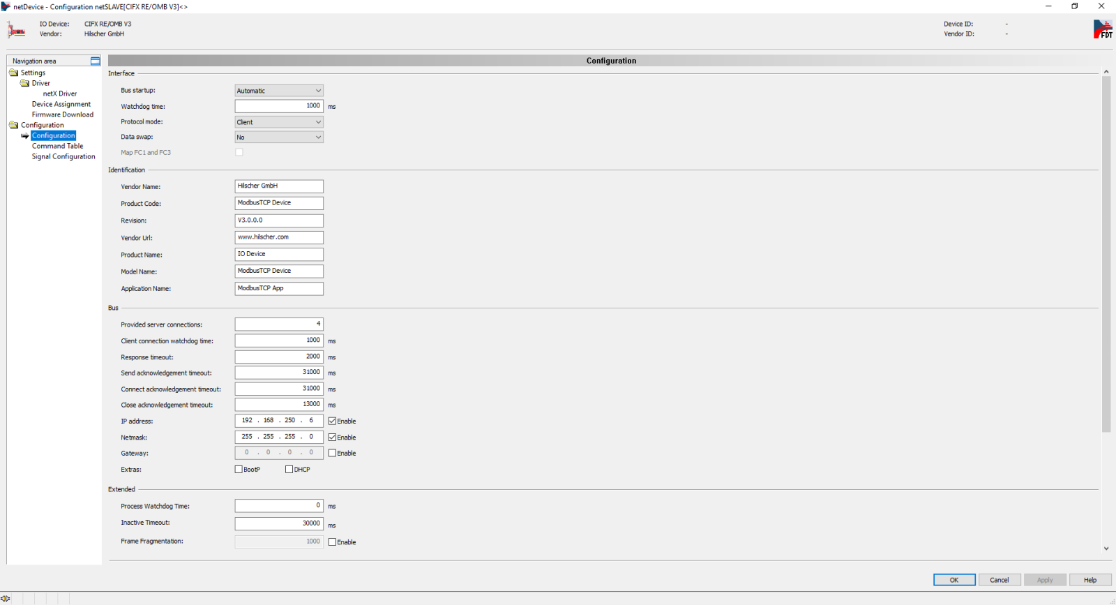
In configuration, set the Protocol mode to Client, and set the IP address and netmask of the card, confirm with Apply/OK.
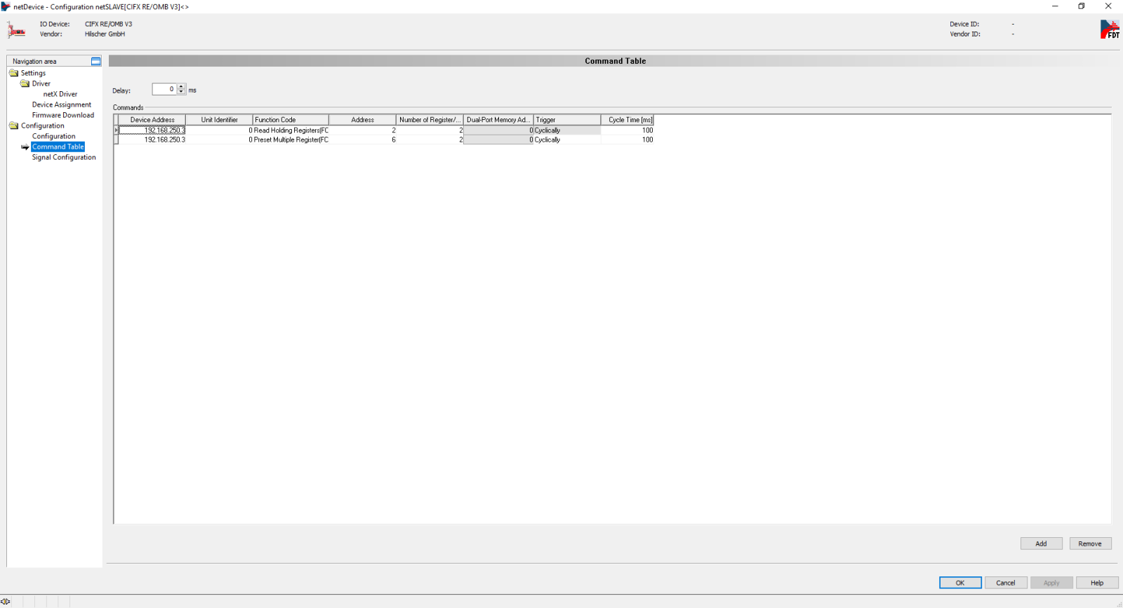
In the Command Table for each register(s) you want to read or write to, Add a row, enter the server IP address, the address and number of the register(s), and the cycle time, confirm with Apply/OK.
By selecting the card, with the right mouse button, you must select Download to load this configuration. You can also Connect (Disconnect) the card to the server. To insert a new configuration or modify the existing configuration the card must be disconnected. To perform the following tests the card must be connected.
To check the connection, you can look at the board LED as indicated in the troubleshooting section or look in Diagnosis / General Diagnosis .
There are two ways to the Hilscher card to access to OEVIS® as server, via Modbus inspector/device or with the Hilscher device.
For more information about OEVIS® - Modbus environment - Modbus inspector, we recommend reading the dedicated technical notes.
Modbus device
In System/Devices add a Modbus server, configured in Big Endian. At the bottom right configure the name (tag), the variable type, the register type, the starting register address and the number of addresses to use.
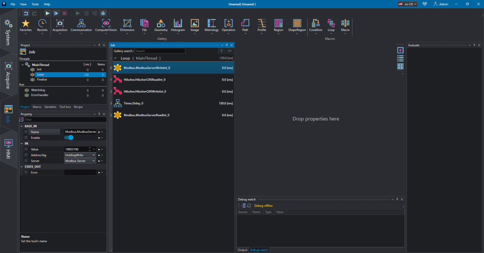
Go to the Job section and between the Communication tools insert ModbusServerWriteInt and ModbusServerReadInt. For the first one complete the Server name and the AddressTag in the IN section. Try inserting a number in Value and Run Once.
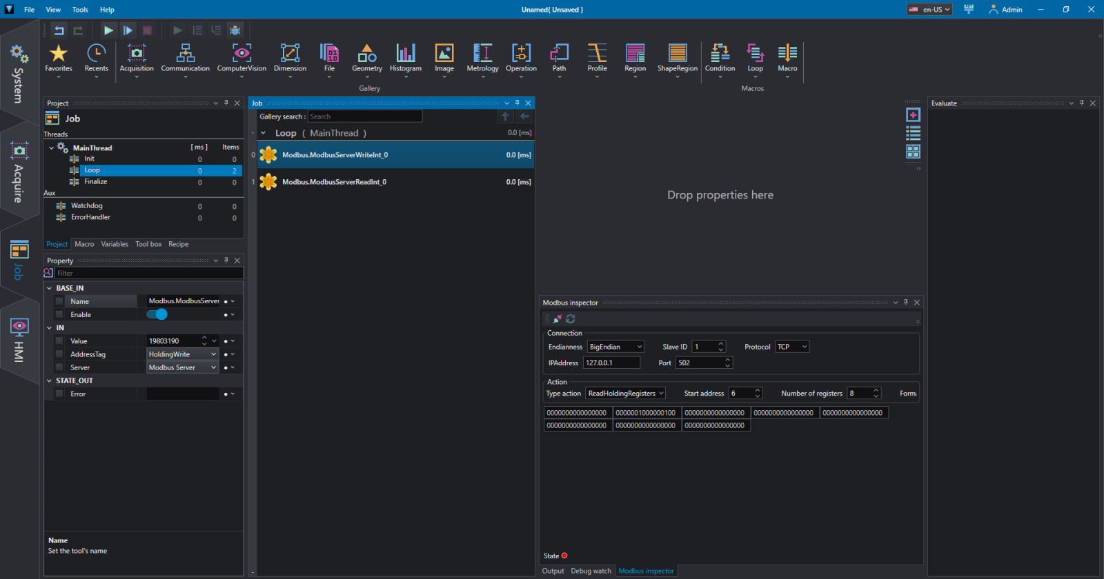
In Diagnosis / Additional Tools / I\O Monitor you can check the contents of the registers, which is useful for debugging.
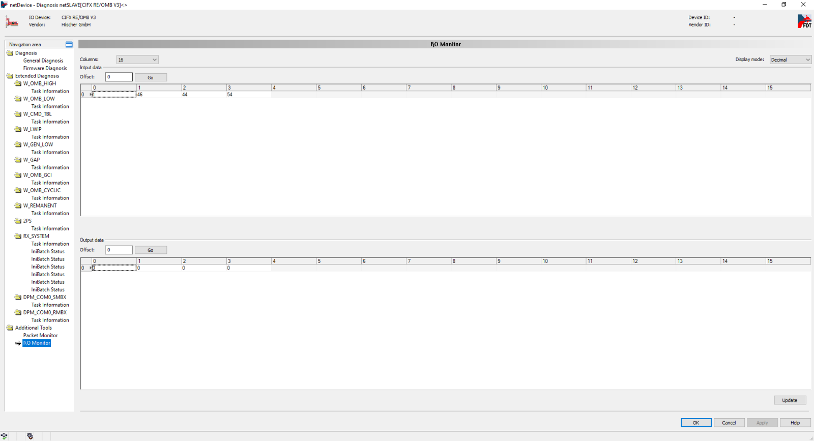
As you can see the Write tool in OEVIS® has inserted the value into the server register which is read into the card in 4 bytes as described in the previous section.
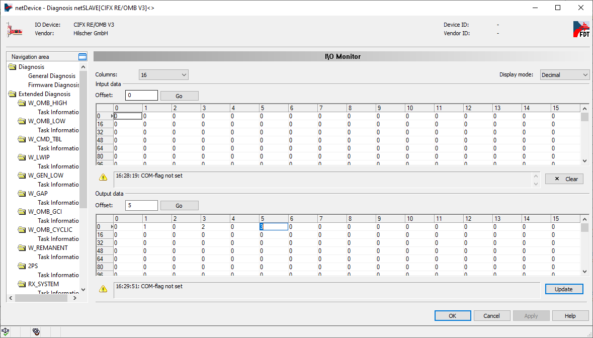
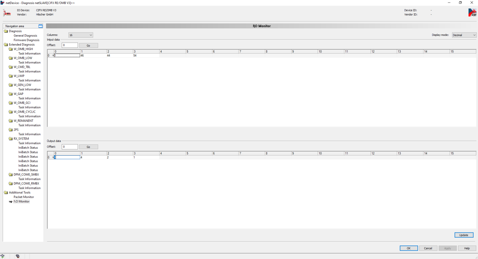
We can also try to write to the server by inserting, for example, the values as in the following figure and pressing the Update button.
To verify this, we can use the Communication / ModbusServerReadInt instruction; complete the Server name and the AddressTag in the IN section. Try Run Once and check the value.
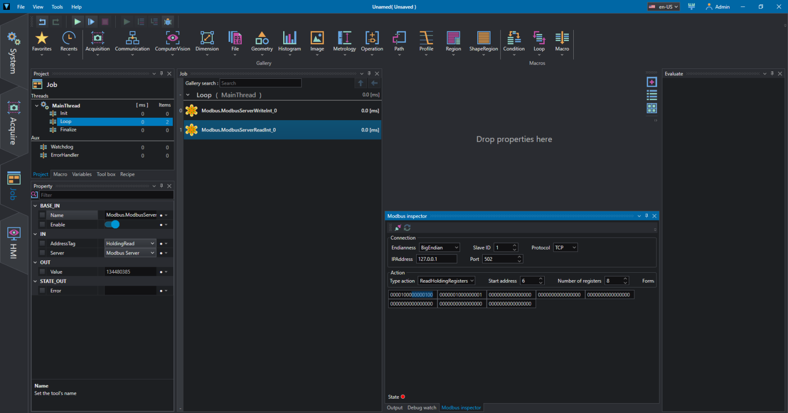
Again, refer to the previous section to understand the format of how the data is transferred.
Hilscher device
In System/Devices add a Hilscher card, selecting the serial number on the right. If this value is not known or there are more cards installed in the system you can help yourself using the Info panel.
As before we add Communication / ModbusServerWriteInt to write a value to the server registry.
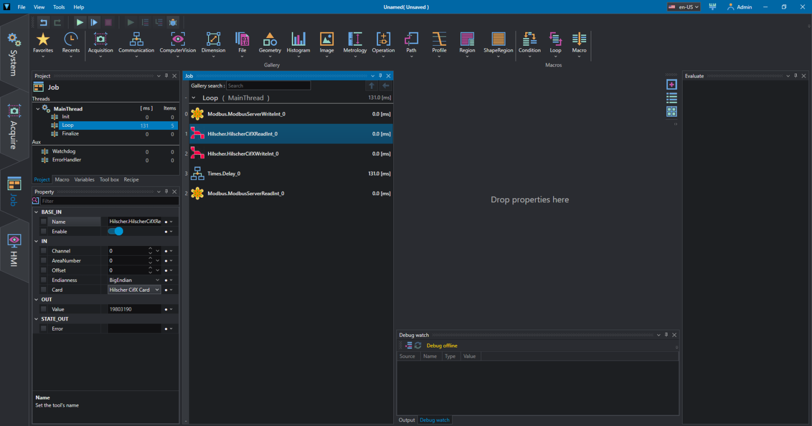
Then we can add Communication / HilscherCifXReadInt to acquire the values that the card reads from the Modbus server (in this case OEVIS® but it could be any server). In the IN section select the Card name, the BigEndian format (usually) and the values Channel, AreaNumber, Offset. Do Run Once and you can read the value in OUT/Value.
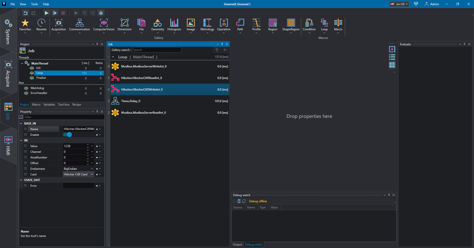
We can also write to the Modbus server with Communication / HilscherCifXWriteInt . In the IN section select the Card name, the BigEndian format (usually) and the values Channel, AreaNumber, Offset. Enter a value of your choice in Value and do Run Once.
To verify this, we can use the Communication / ModbusServerReadInt instruction; complete the Server name and the AddressTag in the IN section. Try Run Once and check the value.
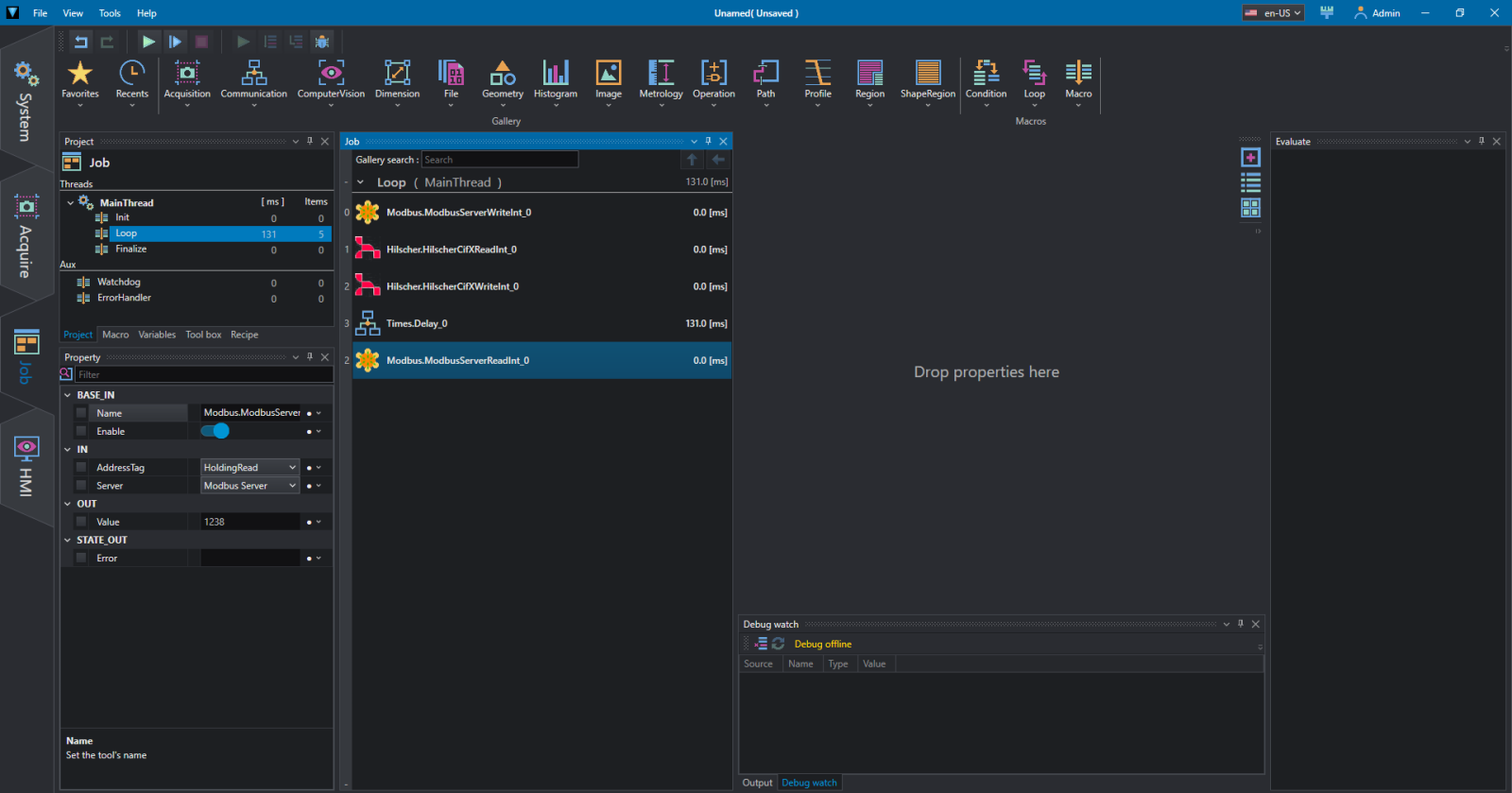
Please note that a delay has been inserted between writing and reading which must be at least equal to the cycle time in Command Table set to the card.
In Diagnosis / Additional Tools / I\O Monitor you can also check the contents of the registers, in Output data, which is useful for debugging.

Using Modbus with Siemens PLC
Modbus is a serial communication protocol created in 1979 by Modicon to connect its programmable logic controllers (PLCs). It is a de facto standard in industrial communication and is currently one of the most widely used connection protocols in the world among industrial electronic devices.
Modbus allows communication between different devices connected to the same network, for example a system that performs a measurement and communicates the result to a PLC. Modbus is also often used to connect a PLC with a supervisor computer (SCADA-OEVIS®).
OEVIS® can be used both as a client and as a Modbus server both on serial port and on ethernet network.
Example of integration between Siemens LOGO! (Modbus Server) and OEVIS® (Modbus Client)
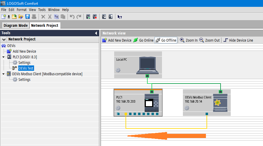
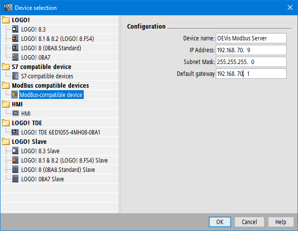
To set LOGO! as a Modbus server, insert a Modbus device into network design.

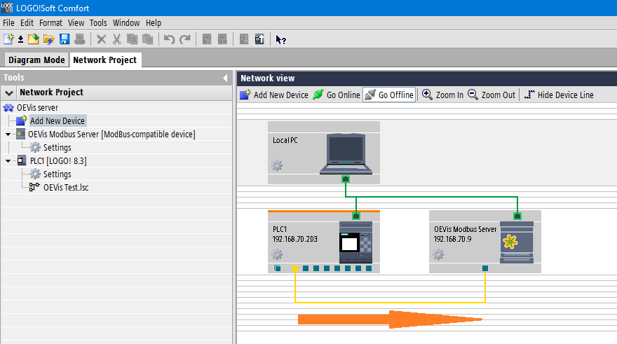
After inserting the device, drag the connection from the Modbus client (OEVIS®) to the PLC LOGO! as shown in the orange arrow in the figure.
Once the connection has been created, double-click on the connection 'wire' to optionally add the data exchange addresses between the devices.
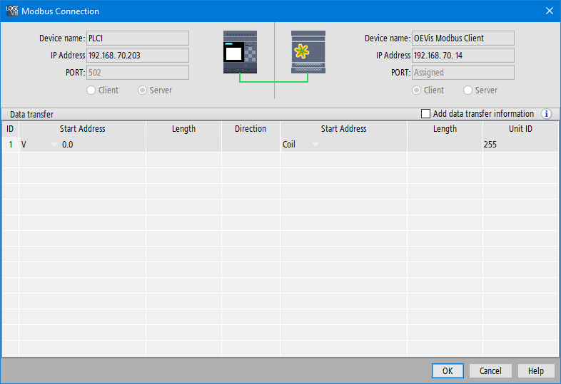
Verify that the IP addresses are correct and that firewalls are not blocking communication.
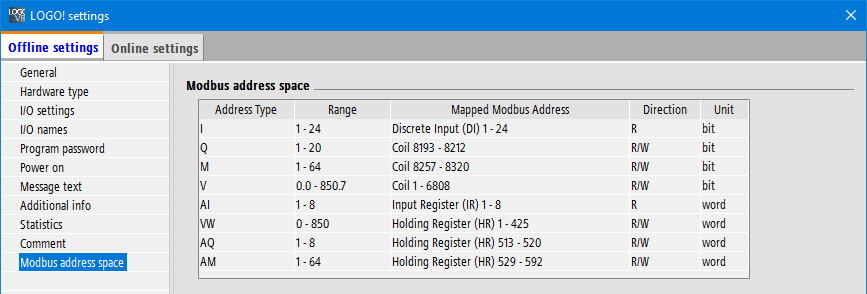
The following table shows the correspondence between the memory areas of LOGO! with the respective Modbus addresses that the CLIENT can access.
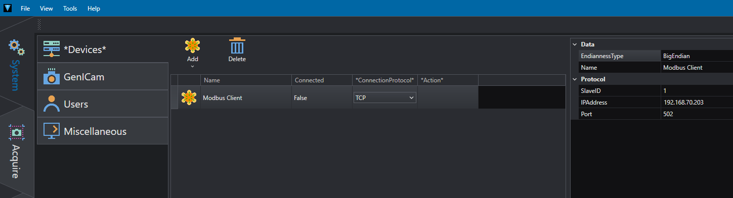
To set OEVIS® as a Modbus client, add a ModbusClient in System/Devices by entering the server's EndiannessType (BigEndian for LOGO!), IPAddress, and Port (usually 502).
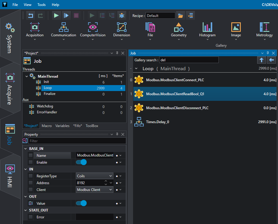
On the Job tab, from the Communication/Modbus menu, enter in order:
- Modbus.ModbusClientConnect to connect the server. In the IN/Client property, select the name of the Modbus client you just created;
- Modbus.ModbusClientReadBool to read, for example, a Boolean value (true/false) as the output of the PLC. In the IN/Client property, select the name of the Modbus client. For the values to be entered in RegisterType and Address, refer to the plc<=>modbus internal address conversion table provided by the manufacturer of the device to which you want to connect. For example, with reference to the LOGO! (Fig. 4) to read the status of output Q1 enter in RegisterType=Coils and in Address=8192 (8193-1);
- Modbus.ModbusClientDisconnect to disconnect from the server. In the IN/Client property, select the name of the Modbus client;
- Times.Delay if you want to repeat the Job continuously with Run instead of individually with Run Once, it is advisable to insert a variable delay between 200-1000 ms between each cycle.
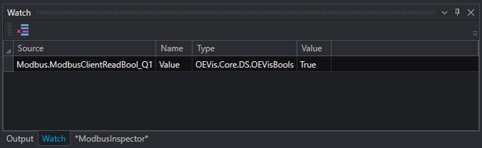
By dragging OUT/Value in the Watch area, you can view its value.
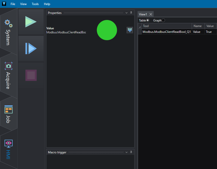
While enabling the HMI flag in Property/OUT, it is possible to display the value in the HMI tab also by applying a template (for details refer to the OEVIS® documentation).
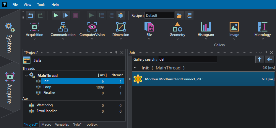
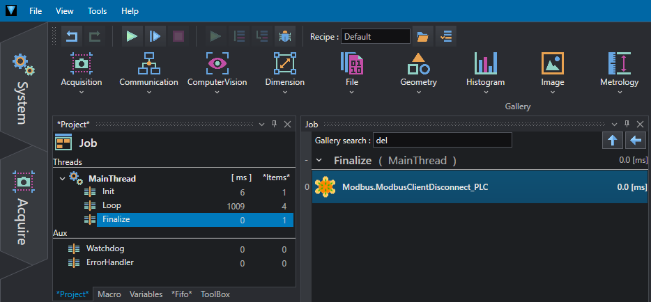
To avoid continuous connections/disconnections to the server, you may want to move the ModbusClientConnect and ModbusClientDisconnect statements to the Init and Finalize of the MainThread.
After inserting the device, drag the connection from the PLC LOGO! to the Modbus server (OEVIS®) as shown in the orange arrow in the figure.
Once the connection has been created, double-click on the connection 'wire' to map the data exchange addresses between the devices. In this example, the Q1 output has been mapped to Modbus address 8193.
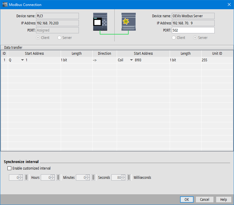
Verify that the IP addresses are correct and that firewalls are not blocking communication.
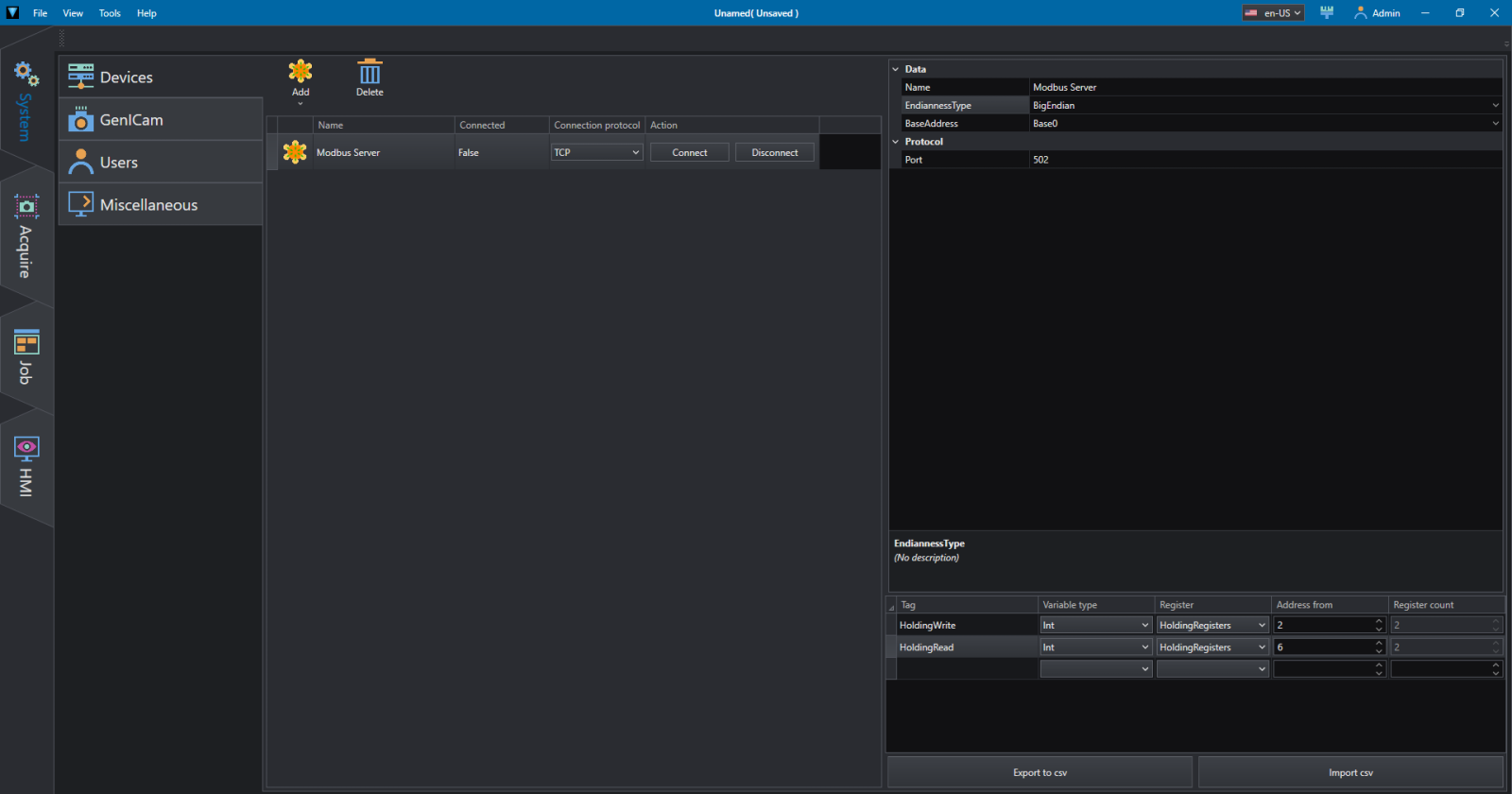
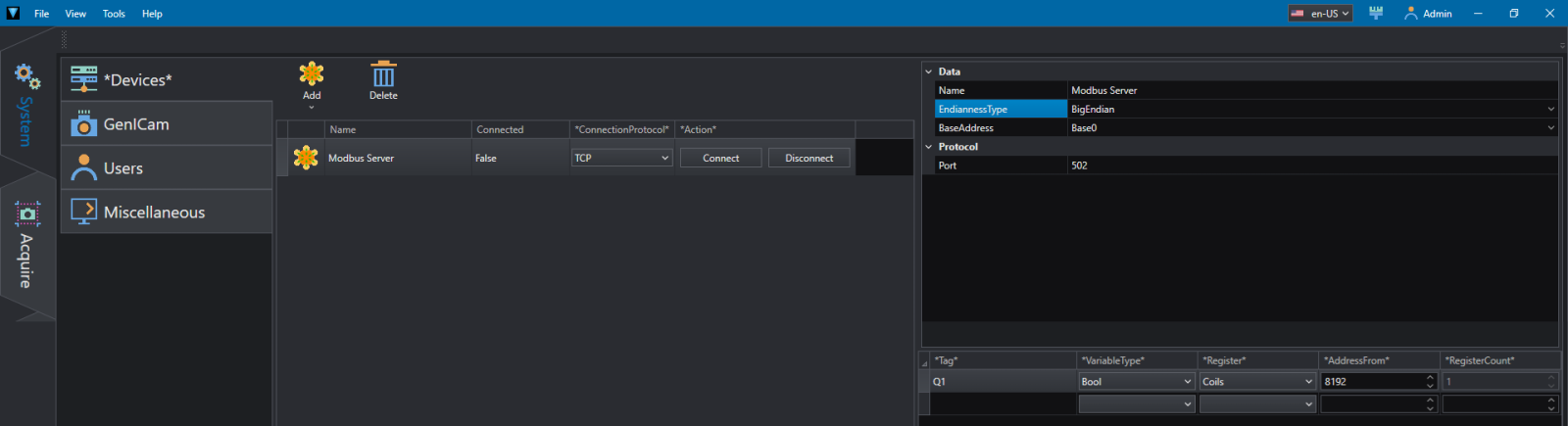
To set up OEVIS® as a Modbus server, add a ModbusServer in System/Devices by entering the server's EndiannessType (BigEndian for LOGO!) and Port (usually 502). As a server, the variables to be used must be indicated with a name of your choice (Tag), in the example to read the status of the Q1 output of the LOGO! as set in Fig.13, enter in VariableType=Bool (1 bit), Register=Coils, AddressFrom=8192 (8193-1). You can turn the server on or off using the Connect/Disconnect buttons.
On the Job tab, from the Communication/Modbus menu, enter in order:
- Modbus.ModbusServerStart to activate the server if not already done in System/Devices. In the IN/Server property, select the name of the Modbus server you just created;
- Times.Delay of 500ms to give time to the server to activate;
- Modbus.ModbusServerReadBool to read, for example, a Boolean value (true/false) as the output of the PLC. In the IN/Server property, select the name of the Modbus server, and in AddressTag, select one of the variables set in System/Devices;
- Modbus.ModbusServerStop to stop the server. In the IN/Server property, select the name of the Modbus server;
- Times.Delay If you want to repeat the Job continuously with Run instead of individually with Run Once, you should enter a variable delay between 200-1000 ms between each cycle.
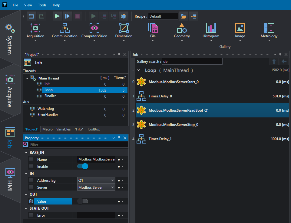
As in the previous case, by dragging OUT/Value in the Watch area it is possible to display the value, while by enabling the HMI flag in Property/OUT it is possible to display the value in the HMI tab also by applying a template (for details refer to the OEVIS® documentation). Likewise, to avoid continuous connections/disconnections to the server, it may be advisable to move the ModbusServerStart and ModbusServerStop statements to Init and Finalize of the MainThread.
The links indicated are valid at the time of publication of this tech note, always refer to the manufacturer's home page in case of missing links.
The information contained in this tech note contains descriptions or characteristics that may vary with the evolution of the products and may not always be appropriate, in the form described, for the specific application case, they must always be understood as a guide and do not in any case constitute a specific constraint or responsibility.
The indication of the aforementioned trademarks and logos is functional for a mere descriptive purpose, all trademarks belong to the legitimate owners; the trademarks of third parties, logos, product names, trade names, corporate and company names mentioned are trademarks owned by their respective owners or registered trademarks of other companies and have been used for educational and explanatory purposes only, without any purpose of infringing current copyrights.