How to integrate ITALA® cameras with Machine Vision Software
Opto Engineering - OEVIS®
Opto Engineering - FabImage®
Cognex - VisionPro
MVTec - Halcon
National Instruments - LabView
The principal purpose of this technical document is to provide an exhaustive guide, offering valuable insights into the integration of the ITALA® camera with the most common Machine Vision software applications.
Each section contained herein is dedicated to a distinct software platform. Within each section, we undertake a comprehensive exploration of the connection process, accompanied by a presentation of detailed step-by-step instructions, complemented by illustrative screenshots.
Our goal is to provide users with a thorough understanding of the procedures involved, ensuring a smooth and proficient implementation of the ITALA® camera across diverse Machine Vision software environments.
Opto Engineering - OEVIS®
This technical note provides a comprehensive guide on how to integrate Opto Engineering's ITALA® series cameras with our powerful OEVIS® machine vision software. By leveraging the industry-standard GenICam protocol, users can seamlessly connect, configure, and control ITALA® cameras to build robust and efficient machine vision applications.
This guide is divided into two main parts:
- Initial Setup: Connecting and configuring the camera using the Acquire tab in OEVIS®.
- Algorithm Development: Programming the image acquisition flow within a Job in OEVIS®.
Prerequisites
Before you begin, please ensure you have the following:
- An Opto Engineering ITALA® camera.
- OEVIS® software installed on your PC.
- The camera is physically connected to your PC's network interface, as described in the ITALA® camera's Getting Started tech note. In particular be sure to have set correctly your network card interface to obtain the maximum performances by the camera.
Part 1: Camera Setup in the Acquire Tab
The Acquire tab is your primary interface for detecting, connecting, and performing the initial configuration of your camera. Please note: adding and configuring your camera in the Acquire tab is a mandatory first step before it can be used in a Job algorithm.
Add a New Camera
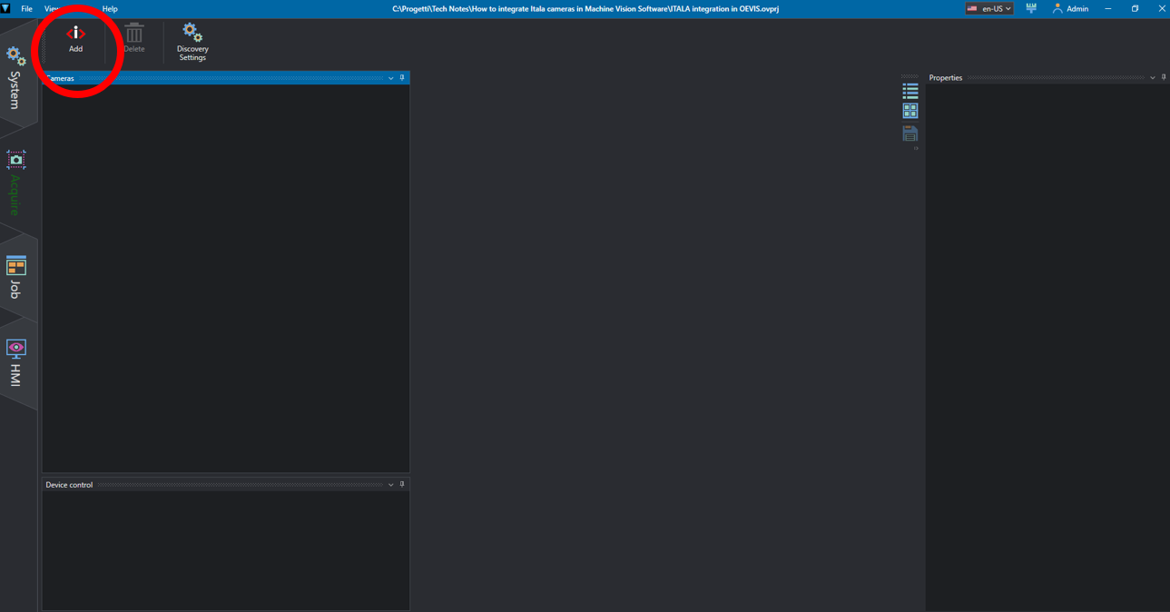
- Navigate to the Acquire tab in OEVIS®.
- In the top-left corner, double-click the Add icon. This action initiates a search for available GenICam devices.
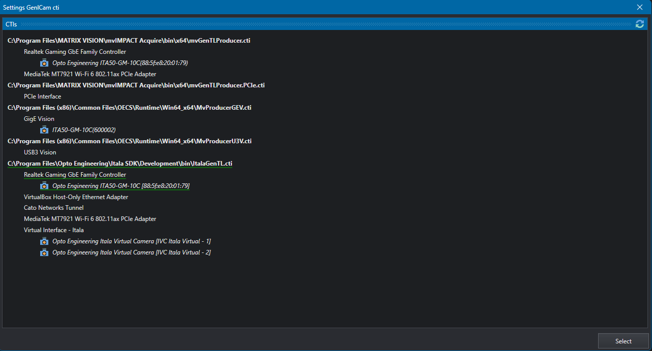
- A window will appear listing all available GenTL producers (.cti files). For optimal performance, we recommend using the manufacturer-specific producer. Select ItalaGenTL.cti.
- Under the selected .cti, you will see the available network interfaces. Look under the correct interface to see a list of all connected ITALA® cameras.
- Click on the name of the camera you wish to use and then click the Select button.
Configure and Test the Camera
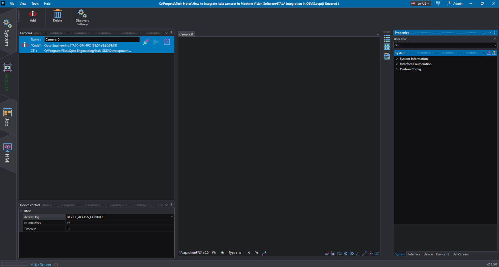
Once the camera is added, the OEVIS® window will update to show the content inside several panels:
- Cameras: On the left, you can see all added cameras. You can right-click a camera to rename it, which is useful for clarity in projects with multiple cameras.
- Device Control: In which you can set the AccessFlag, the size of the GenICam buffer, and the timeout.
- Image Preview: The central area displays the live or captured image from the camera.
- GenICam Tree: On the right, the complete GenICam feature tree is available, allowing you to configure all camera parameters such as exposure, gain, and trigger modes.
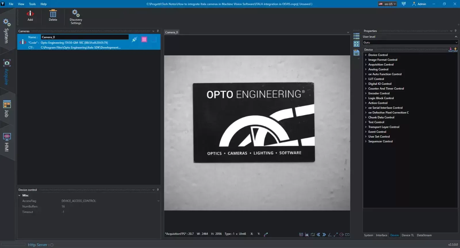
Follow these steps to start streaming:
- In the Cameras List, click the Connect icon (shaped like a plug) next to your camera's name.
- Use the GenICam Tree on the right to adjust the camera settings (e.g., ExposureTime, Gain) to fit your application's requirements.
- Click the Play icon to start the live acquisition and see the resulting image in the preview window.
Part 2: Programming Image Acquisition in the Job Tab
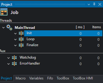
The Job tab is where you develop your machine vision algorithm. OEVIS® jobs are structured around threads, which are divided into three execution phases:
- Init: Runs once when the program starts. Ideal for camera initialization and setup.
- Loop: Runs continuously until the program is stopped. This is where image acquisition and processing occur.
- Finalize: Runs once when the program stops. Used for safely disconnecting and releasing resources.
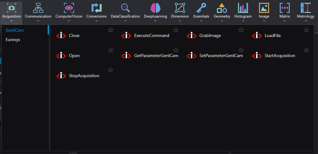
All camera-related tools are located in the tool palette under Acquisition > GenICam. These tools are a direct implementation of the GenICam standard.
1. Initialization (Init section)
First, prepare the camera for acquisition. We recommend placing the following tools in the Init section.
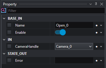
- Open: This tool establishes a connection with the camera hardware.
- Add the Open tool to the Init section.
- OEVIS® automatically links the camera handle (e.g., Camera_0) created in the Acquire tab to the tool's properties.
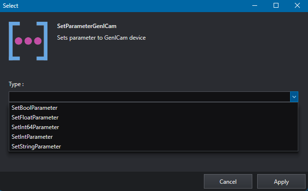
- SetParameterGenICam: This tool allows you to programmatically change camera settings. We recommend setting in the Init section all the camera parameters which will remain the same during every software loop and so should be set only once when the program starts. Typical examples are the exposure time, trigger mode, trigger source, but it depends on your application. In this example we are going to set the exposure time. Please notice that each parameter has its own data type, so be sure to select the correct one for the parameter that you want to interact with.
- Add the SetParameterGenICam tool. A window will prompt you to select the parameter type. For exposure time, choose SetFloatParameter.
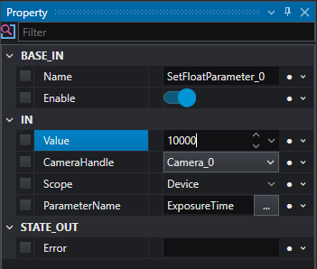
- In the tool's properties, click the ellipsis icon (...) next to ParameterName.
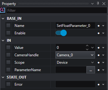
- Navigate the GenICam tree to find ExposureTime, select it, and click Select.
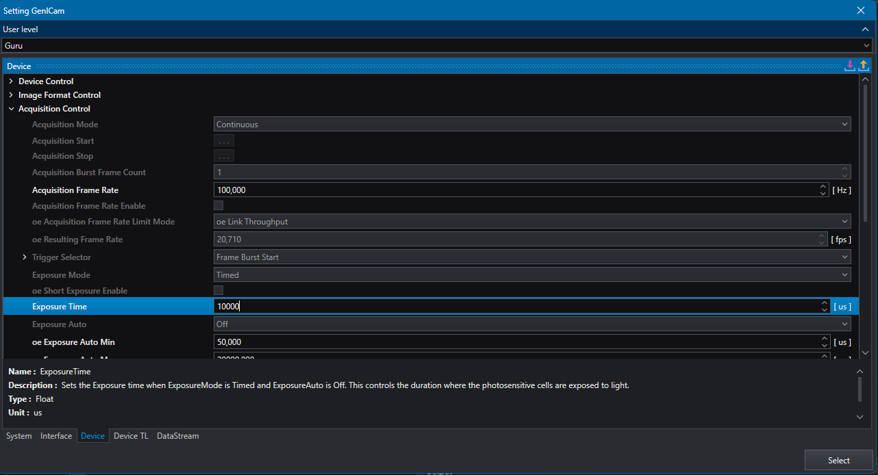
- Set the desired Value in microseconds (e.g., 10000).
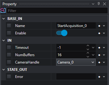
- StartAcquisition: This tool commands the camera to start acquiring images.
- Add the StartAcquisition tool. You can set a Timeout (default is -1 for infinite) and the number of Buffers to be allocated.
2. Image Acquisition (Loop section)
With the camera running, you can now grab images in the Loop.
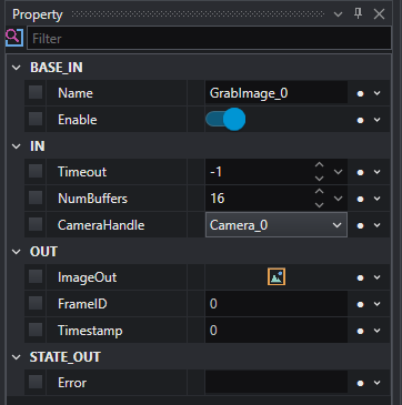
- GrabImage: This tool retrieves the oldest available image from the acquisition buffer.
- Add the GrabImage tool to the Loop section.
- The primary output, ImageOut, can be connected to other processing tools or to an HMI for display.
- You can also access frame-specific metadata like FrameID and Timestamp.
Pro Tip: You can also place SetParameterGenICam tools within the Loop to dynamically change settings between grabs. However, be aware that some parameters (e.g., Width, Height) can only be modified when the acquisition is stopped.
3. Finalization (Finalize section)
Properly closing the connection is crucial for system stability. Place the following tools in the Finalize section.
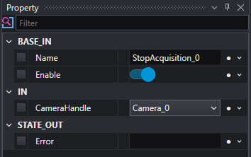
- StopAcquisition: This tool halts the image acquisition stream. The camera remains connected and its parameters are still accessible. This is useful if you need to change a parameter that cannot be modified during live acquisition.
- Add the StopAcquisition tool. The CameraHandle will be linked automatically.
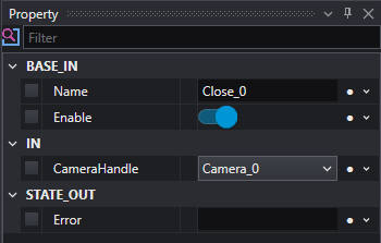
- Close: This tool completely closes the connection to the camera, releasing it for use by other applications. This should be the final camera-related command in your program.
- Add the Close tool. Like the other tools, the CameraHandle is all that is required.
Conclusion
By following this guide, you have successfully integrated your ITALA® camera with OEVIS®. You have learned how to establish a connection in the Acquire tab and how to build a robust acquisition sequence in the Job tab using the Init, Loop, and Finalize structure.
You are now ready to expand your Job by adding image processing, measurement, and decision-making tools to create a complete machine vision solution. For more advanced topics and a full list of available tools, please refer to the official OEVIS® software documentation or contact our technical support team.
Opto Engineering - FabImage®
Connect the camera, to do that follow the guidelines that you find in the Getting Started. Once the camera is properly connected, open FabImage Studio.
With FabImage® you have the possibility to use either GigEVision or GenICam protocols, Itala cameras are compatible with both of them. We will see first how to set up the connection using GigEVision and then how to do it with the GenICam protocol.
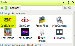
GigE Vision
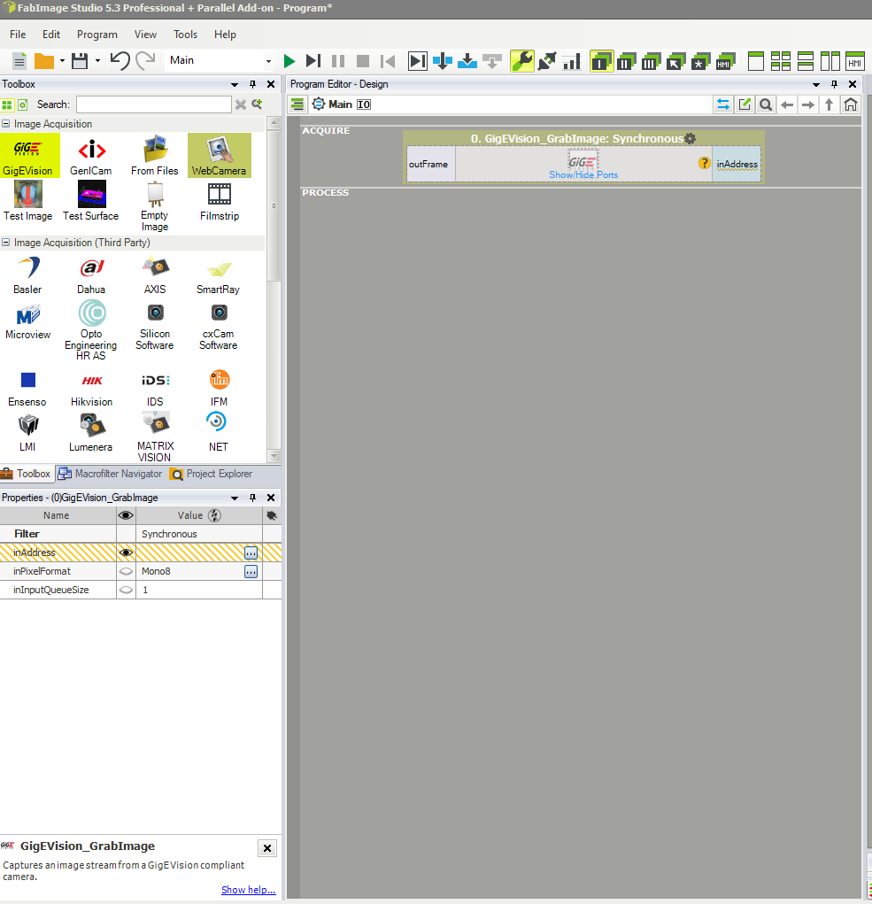
In the Toolbox section, which is usually on the left, double-click on GigEVision, you can find it under the tab Image Acquisition.
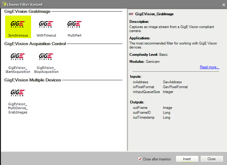
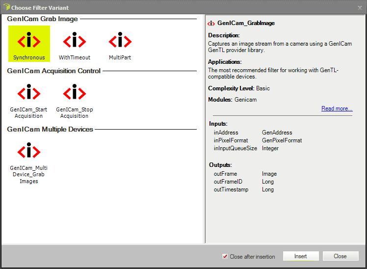
A new window will open that allows you to choose among different filter variants. Here you can choose to grab an image either in synchronous mode or with a timeout. The main difference between the two modes is that with Synchronous the program will wait for an image for an indefinite period of time, stopping the execution of the program. Using WithTimeout you can set a time in milliseconds that will be the maximum time that the program will wait for the image to come, if no image comes it will return a Nil.
For this example, we will go with Synchronous, so double-click on that. This will add the filter to the program editor.
Now click on the recently added filter to show the properties, these will be shown in the Properties tab, which is usually on the bottom left of the program as a default setting. You will notice that the program is asking for an input, which is the address of the camera since the inAddress variable has an orange-lined background. Click on the icon with the three dots to assign an address to the filter.
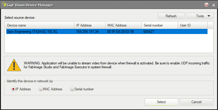
This will open up the GigE Vision Device Manager which will display some useful information such as a list of the cameras connected to the PC, their IP Address, the MAC address, and the Serial Number. Select the camera that you want to connect and click on Select.
Now drag the output of the filter, the outFrame, to the data preview. Run the program to see the live image being captured.
If you want to control the parameters of the cameras there are two ways. One will be using the integrated tool inside FabImage, the other is using the filters. If you need to quickly set your parameters the first method is the easiest to do however, if your parameters need to change dynamically during the execution of the project, you have to do it with the filters.
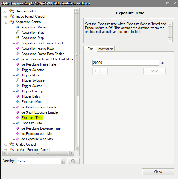
To access the tool go to Tools > Manage GigE Vision Devices…, in the window that will appear select the camera that you want to manage by double clicking on its name. This will open the GenICam tree of the camera, by navigating to the wanted parameter you will see a tab with some information and an editor.
Once you are done editing the parameters of the camera, simply click on Close to close the window.
The other way to change the parameters is by using FabImage’s filters. In the FabImage toolbox go down to the Program I/O tab, open it, and select the GigEVision I/O.
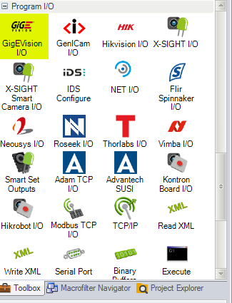
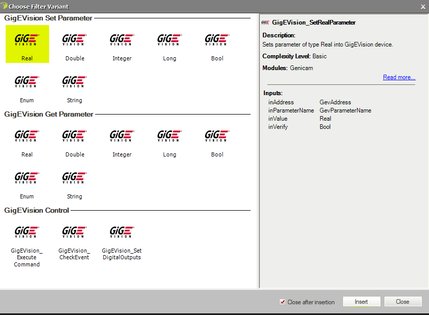
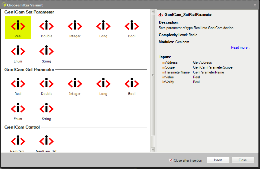
This will open a window with all the possible options of the GigEVision filter, you can either Set a Parameter, Get the value of a parameter, or Execute commands. In this case, you also need to choose the type of parameter that you are going to modify. If we keep the exposure time as an example we can select Real. To do that just double-click on it, this will add the filter to the program editor.
Now click on the filter once to select it, in this way, you will be able to see the properties of the filter. Here you need to specify the Address of the camera, following the same procedure used for the GrabImage filter.
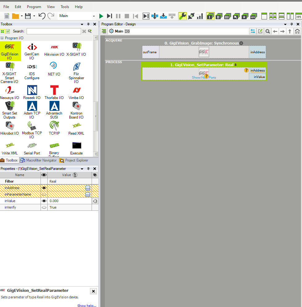
You will need to specify the name of the parameter in the inParameterName variable. To do that click on the icon with the three dots, this will open the GenICam tree of the camera. Navigate to the parameter that you want to access and double-click on it. Now you just need to put the value of the parameter that you want to set in the inValue field.
When you are setting a parameter of the camera always put the filters before the acquisition of the image, if you want to see the changes straight away, otherwise in the first iteration of the project you will start the acquisition with the values already set in the camera.
GenICam
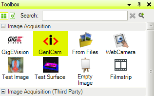
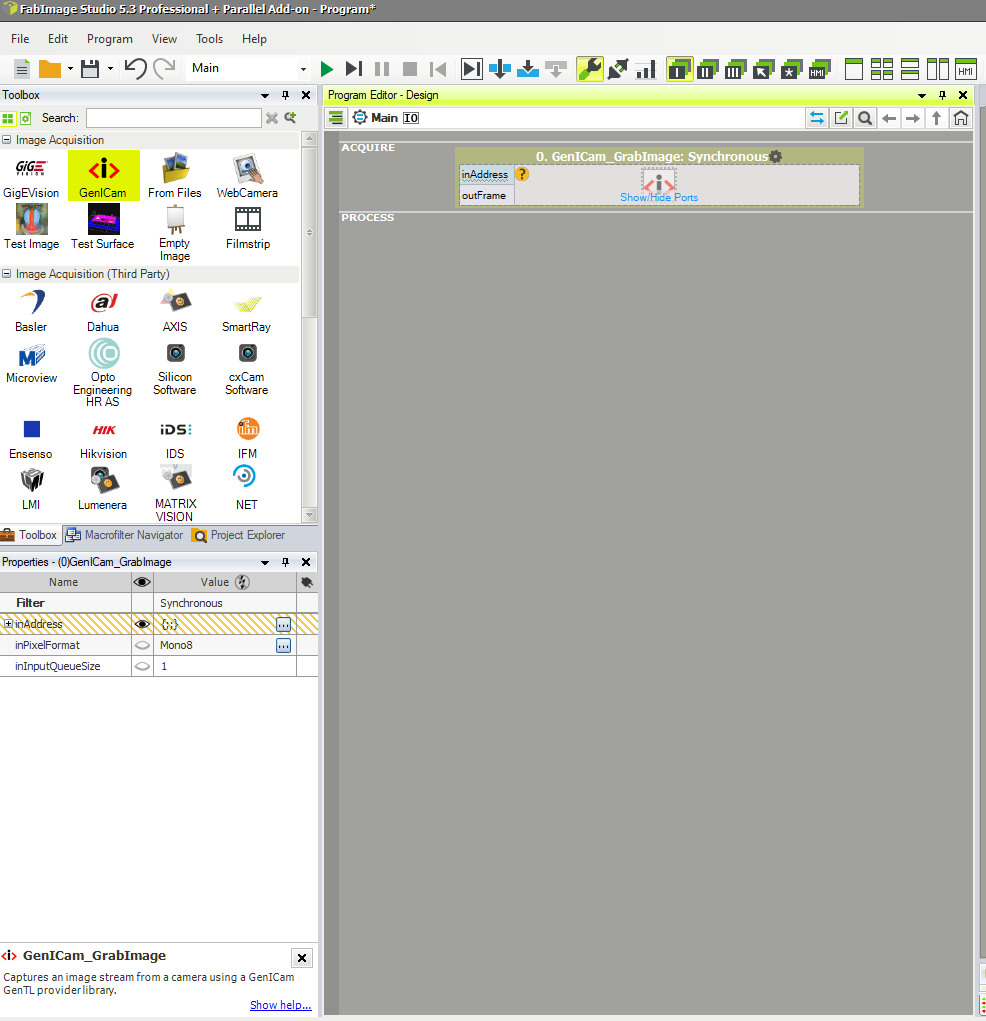
On the left, you will find a section called Toolbox, here double click on GenICam, and you can find it under the tab Image Acquisition.
A new window will open that allows you to choose among different filter variants. Here you can choose to grab an image either in synchronous mode or with a timeout. The main difference between the two modes is that with Synchronous the program will wait for an image for an indefinite period of time, stopping the execution of the program. Using WithTimeout you can set a time in milliseconds that will be the maximum time that the program will wait for the image to come, if no image comes it will return a Nil.
For this example, we will go with Synchronous, so double-click on that. This will add the filter to the program editor.
Now click on the recently added filter in order to show the properties on the tab on the bottom left of the program. You will notice that the program is asking for an input, which is the address of the camera since the inAddress variable has an orange-lined background. Click on the icon with the three dots to assign an address to the filter.
This will open up the General Device Manager which will display all the GenTL infrastructures. Locate the one called Opto Engineering GenTL 1.5 Producer, open it, and select the Network Card Interface that you want to use, open that and you will see the name of the camera connected. Click on that and then click Select.
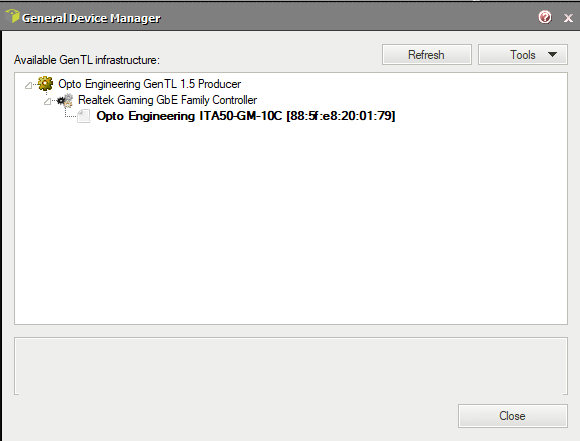
Now drag the output of the filter, the outFrame to the data preview. Run the program to see the live image being captured.
If you want to control the parameters of the cameras there are two ways. One will be using the integrated tool inside FabImage, the other is by means of the filters. If you need to quickly set your parameters the first method is the easiest to do. However, if your parameters need to change dynamically during the execution of the project, you have to do it with the filters.
To access the tool go to Tools > Manage GenICam Devices…, in the window that will appear, locate the GenTL infrastructure named Opto Engineering GenTL x.x Producer, open it, and open also the correct Network Card Interface that you want to use. Double-click on the name of the camera. This will open the GenICam tree of the camera, by navigating to the wanted parameter you will see a tab with some information and an editor.
Once you are done editing the parameters of the camera, simply click on the Close button in order to close the window.
The other way to change the parameters is by using FabImage’s filters. In the FabImage toolbox go down to the Program I/O tab, open it, and select the GenICam I/O.
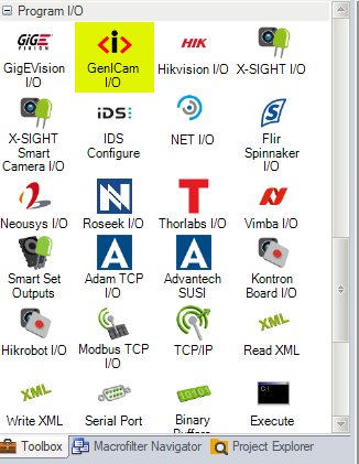
This will open a window with all the possible options of the GenICam filter, you can either Set a Parameter, Get the value of a parameter, or Execute commands. In this case, you also need to choose the type of parameter that you are going to modify. If we keep the exposure time as an example we can select Real. To do that just double-click on it, this will add the filter to the program editor.
Now click on the filter once to select it, in this way, you will be able to see the properties of the filter. Here you need to specify the Address of the camera, following the same procedure used for the GrabImage filter.
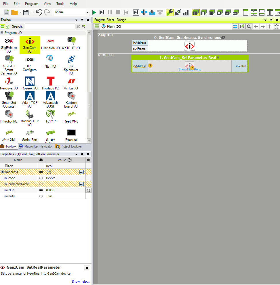
You will need to specify the name of the parameter in the inParameterName variable. To do that click on the icon with the three dots, this will open the GenICam tree of the camera. Navigate to the parameter that you want to access and double-click on it. Now you just need to put the value of the parameter that you want to set in the inValue field.
When you are setting a parameter of the camera, always put the filters before the acquisition of the image if you want to see the changes straight away, otherwise in the first iteration of the project you will start the acquisition with the values already set in the camera.
Cognex - VisionPro
Connect the camera, to do that follow the guidelines that you find in the Getting Started. Please notice that this software is not a product of Opto Engineering, but it has been developed and is maintained by Cognex.
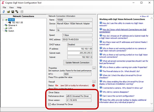
Once the camera is properly connected, open Cognex GigE Vision Configurator to ensure that the performance driver is correctly installed and set.
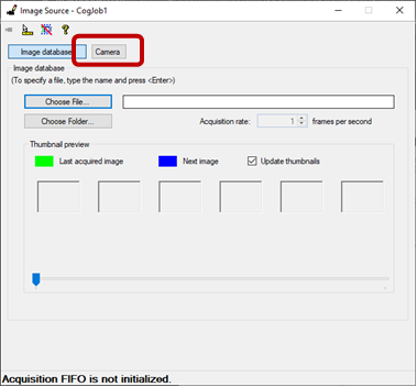
Now open VisionPro QuickBuild, this will be used to integrate the camera and create the project with VisionPro. In order to import the camera double click on Image Source.
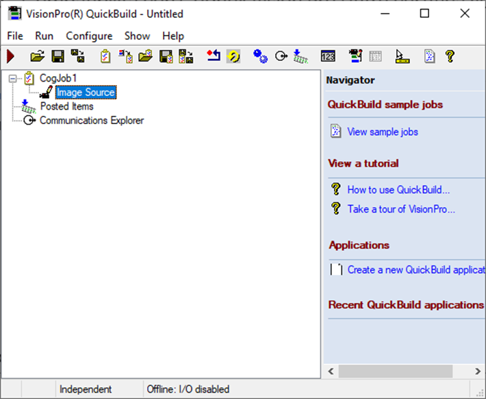
Two windows will open up, use the Image Source window, here you will set the source used to acquire the image. You can either select a camera or acquire an image, we will select a camera. Double-click on the Camera button.
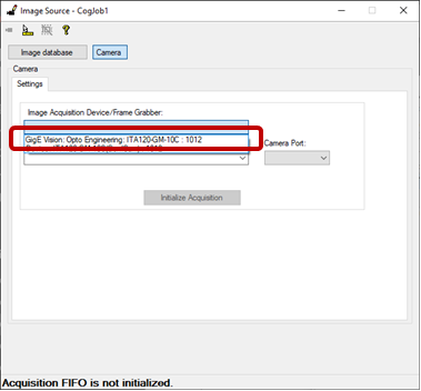
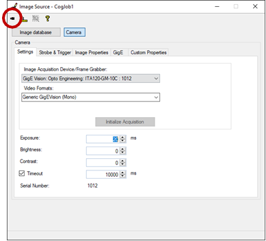
This will show the camera settings, from this window you can select the camera to use. Click on the combo box to see the list of available cameras. Select the entry related to the Itala Camera which starts with GigE Vision, in this way, you ensure to use GigE Vision communication interface.
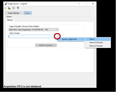
Click on the descending arrow in the video format box to select the desired pixel format for the image acquisition.
To start the acquisition of the camera click on Initialize Acquisition.
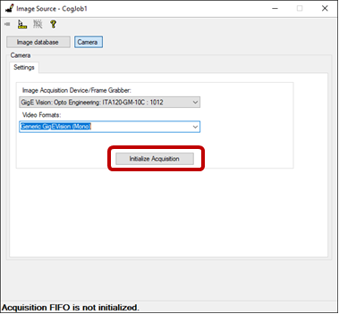
Click on the camera icon on the top left of the window to see a live preview of the image acquired.
You will notice that also other tabs appeared in the window, you can use these to control the parameters of the camera.
MVTec - Halcon
Connect the camera, to do that follow the guidelines that you find in the Getting Started. Also, make sure to have downloaded the latest version of GigEVision interface for Halcon.
Once the camera is properly connected, open Halcon HDevelop. Please notice that Halcon is not an Opto Engineering Product but it has been developed and is maintained by MVTec.
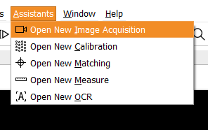
Go to Assistant and click on Open New Image Acquisition, this will open an image acquisition assistant window which will guide you through the connection with the camera.
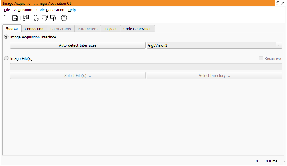
The assistant allows you to select the camera to connect, control the camera parameters, and capture the images.
In the Source tab, you need to select the correct acquisition interface. Select the option Image Acquisition Interface and from the dropdown menu select GigEVision2 as the interface that you are going to use.
Then go to the Connection tab, here you can choose the camera to connect with Halcon. From the drop-down menu close to the device parameter you can select the camera. Notice that if you do have only one camera connected this will be shown. Once you have selected the camera click on Connect. This will start the connection with the camera, you can use the buttons Snap or Live to either acquire a single image or to start the acquisition of a stream of images.
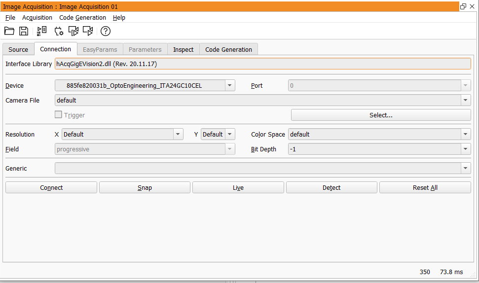
Once the camera is connected you will be able to access the tabs EasyParams and Parameters which allow for the control of the camera parameters. You can use the tab Parameters to access and modify the GenICam tree of the camera. Note that if you are not connected to the camera, you will not be able to access these two tabs.
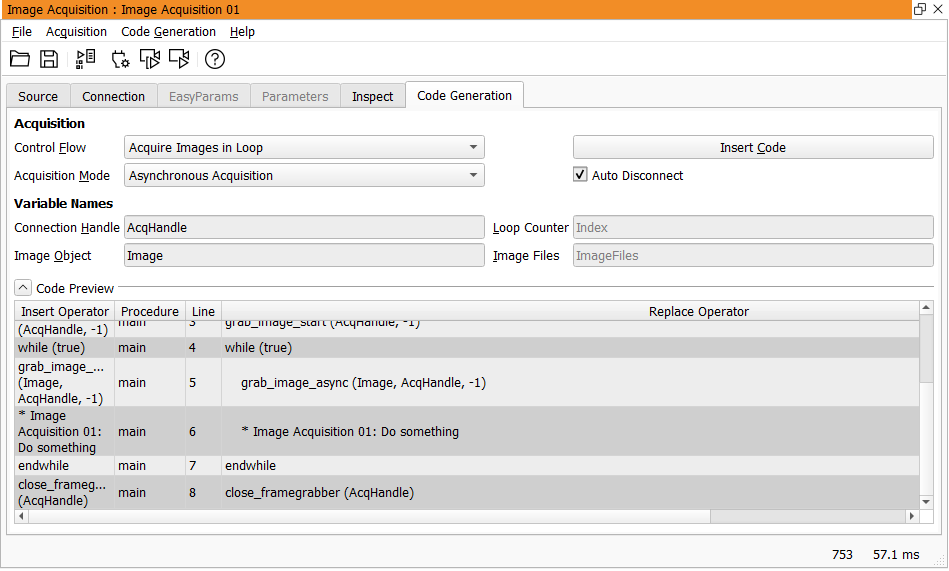
Once you set up the camera you can generate the code to use in HDevelop for the image acquisition. To do that go to the Code Generation tab, select the Control Flow and the Acquisition mode, and then click Insert Code. You will then find the generated code in the Program Window of HDevelop.
National Instruments - LabView
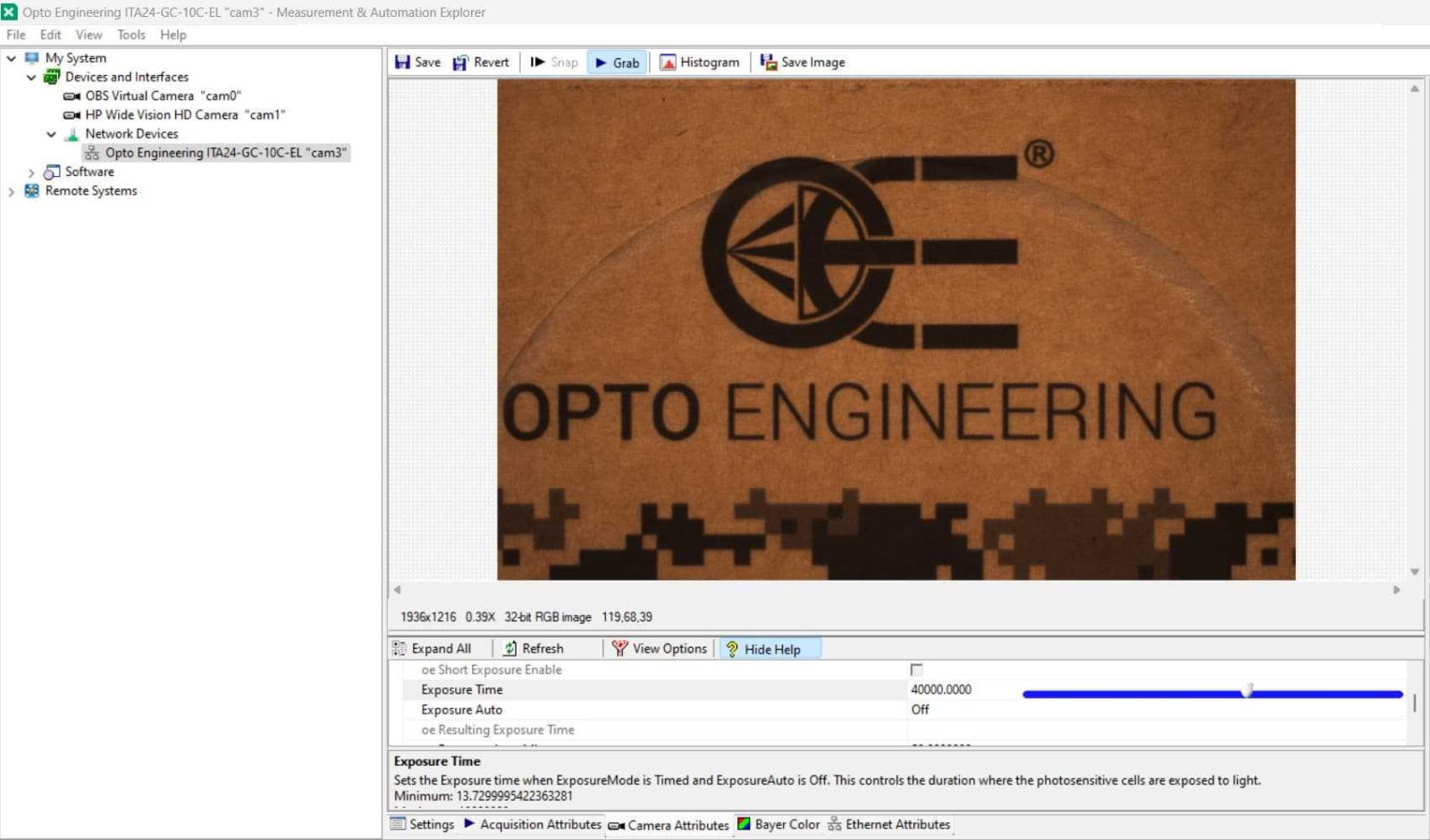
Connect the camera, to do that follow the guidelines that you find in the Getting Started. Once the camera is properly connected, open NI MAX. Please notice that this software has been developed and is maintained by National Instruments.
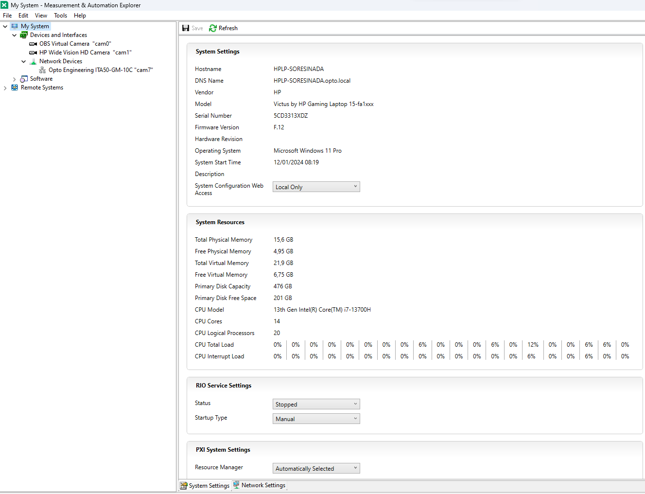
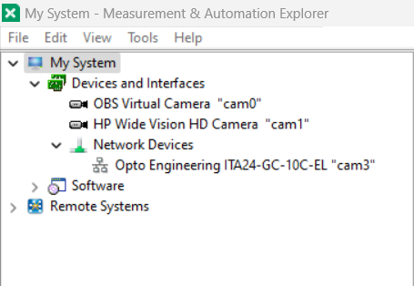
You should see a window that displays some information about the PC that you are using. In order to see the camera you need to use the menu on the left. Go to My System > Devices and Interfaces > Network Devices. Here you should see a list of all the cameras connected to the PC. Opto Engineering cameras will be seen as Opto Engineering NAME OF THE CAMERA “cam_number”.
Click once on the name of the camera to access its parameters. The central window of the software will change and it will show some general information about the device such as the name, the IP address, the model name, and the serial number.
On the top, you will see two buttons to snap an image or to start the grabbing of a stream of images. At the bottom, you can change the information displayed in the central window and you will be able to access the camera parameters. In particular:
- Acquisition Attributes: allows to show the image, allows to change the pixel format, and to select a Region of Interest.
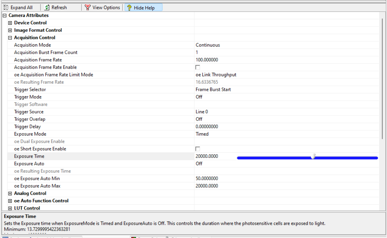
- Camera Attributes: displays the GenICam tree with all the camera parameters and allows you to change them.
- Bayer Color: can be used to perform White Balance operation.
- Ethernet Attributes: contains the attributes related to ethernet connection.
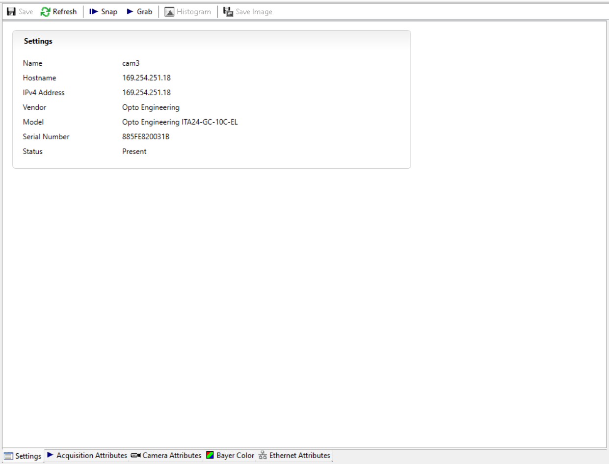
You can switch to Camera Attributes and navigate to Exposure Time to select a proper value. You will find it under Acquisition Control.
Once you set your camera parameters you can click on Grab to start the acquisition of the camera. You will see the image displayed in the center of the window.