Using LTDVE Controllers with OEVIS
System Setup
Example of setting the controller
Many machine vision applications rely on light controllers to ensure optimal illumination intensity and precise, repeatable synchronization between lights and cameras.
In addition, light controllers play a key role in regulating and stabilizing the electrical power delivered to LED illuminators, ensuring safe operation and consistent optical output over time.
LTDVE controllers are compact devices that integrate power supply conditioning, intensity control, timing generation, and advanced triggering functions. They can be configured via a PC using either an RS485 serial connection or an Ethernet interface. All configurations are stored in non-volatile memory, allowing the controller to automatically resume operation after a power cycle.
This technical note describes how to integrate an LTDVE controller within the OEVIS software.
A detailed description of the LTDVE controller parameters or the OEVIS functions and workflow is outside the scope of this document. For more in-depth information, please refer to the official LTDVE controller and OEVIS documentation.
System Setup
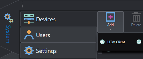
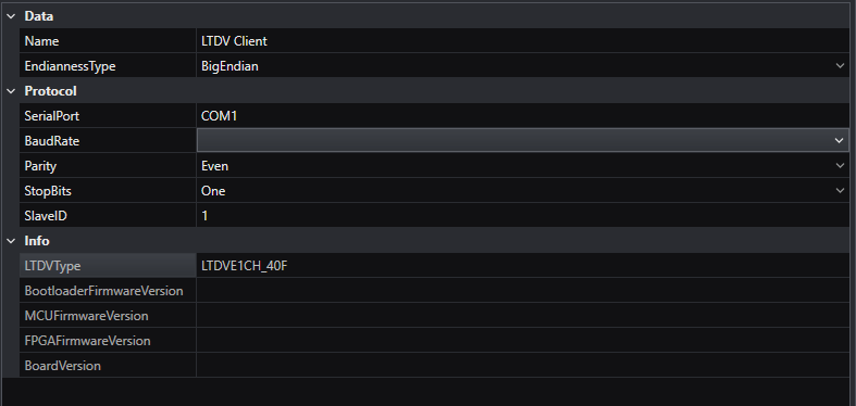
From the System/Device tab, add LTDV Client as a new device.
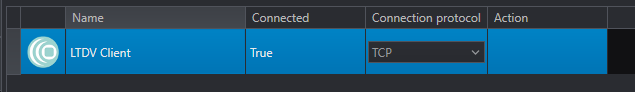
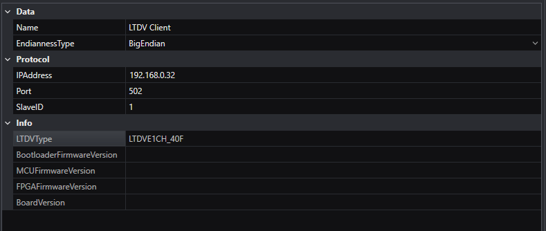
By clicking on the device, you can select the communication protocol choosing between either TCP or Serial. In both cases, on the right, you will see information about the device, and you can setup the communication.
If you use TCP, the default IP address is 192.168.0.32 and the port is 502. While for serial communication the default baud rate is 9600 bps, the default parity is even.
Example of setting the controller
In this example we are going to show how to use the controller as a master to trigger both the camera and the light. The controller relies on its internal oscillator as the clock source to generate a synchronization signal that is distributed to both devices.
In this configuration, a single synchronization signal is used to trigger both the camera and the light. However, the LTDVE controller allows the definition of multiple independent synchronization signals, enabling separate triggering of several external devices. These signals can be generated using the internal oscillator as a common master clock or synchronized to external signals connected to the LTDVE inputs.
The following steps will be described:
- Set the LTDV Pulse Generator to shape the “synchronization signal”. We will conventionally refer to this “synchronization signal” as “PG-signal” or “PG”.
- Use the “PG-signal” to synchronize the trigger to the lighting and to shape the lighting pulse duration and duty-cycle. We will refer to the output to control the lighting as “LD”.
- Use the “PG-signal” to synchronize the trigger to the camera acquisition. We will refer to the output to trigger the camera as “SH”.
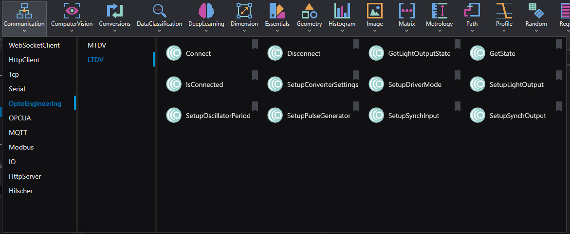
In OEVIS’s Job tab where you design the project, all the tools related to the LTDVE controller can be found in the tool library collection on the top bar, under Communication/Opto Engineering/LTDV.
We recommend handling the controller settings in the Init section of your project, only use the Loop section to set controller’s parameters which should change dynamically while running the software. Also, for the sake of clarity, we recommend creating a macro filter in which you should put all the tools related to the configuration of the controller.
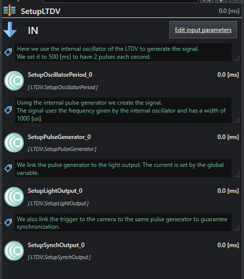
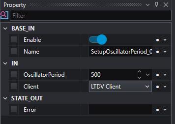
Using this logic, we are ready to start working with the controller. The first thing is to set the period of the internal oscillator. This will work as our internal master-clock, setting the “PG-signal” repetition rate. To do this let’s add the tool named SetupOscillatorPeriod. This tool requires as input the oscillator period, expressed in milliseconds, and the client name. The latter can be selected from a list of the connected devices; in this example, the client is named LTDV client.
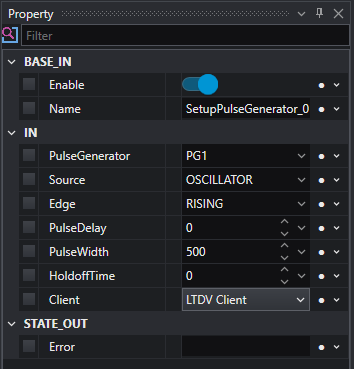
Now we can shape the “PG-signal” by using the tool SetupPulseGenerator. The inputs of this tool are:
- PulseGenerator: Each controller has several pulse generators; with this parameter you select which one you want to access and to set. In our example, we use the PG1.
- Source: You select which signal you want to use as a clock of the “PG-signal”. In our example, the source is the LTDV internal oscillator.
- Edge: Select which source signal’s edge is sampled to generate the pulses of the “PG-signal”. Options are Rising, Falling and Both.
- PulseDelay: Set the delay between the source signal selected edge and the rising edge of the “PG-signal” pulses, expressed in microseconds.
- PulseWidth: Set the duration of the "PG-signal" pulses, expressed in microseconds. Note that the repetition rate of these pulses is set by the Source repetition rate and the selected Edge to be sampled. Hence, setting the PulseWidth is also setting the duration of the Toff time between two pulses of the “PG-signal” and its duty-cycle. In our example the “PG-signal” will be used to control the light, hence the PulseWidth, will also determine the light pulses duration and its duty-cycle, together with Source repetition rate and Edge sampled.
- HoldoffTime: Set the minimum time between two pulses of the “PG-signal”, expressed in microseconds. This parameter is particularly important when the Source is an external triggering signal. When using the internal oscillator as per our example, it is not needed, or it is enough that the sum of PulseWidth and HoldoffTime is lower than the oscillator period.
- Client: Select which device do you want to access to, in our example this is the “LTDV Client” previously added.
We have now the signal that will control the synchronization of both the light and the camera, the next operation is to use this “PG-signal” to set the outputs to the two devices. We will start with the light, but the order of the next two operations can be changed.
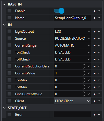
To set the “LD” output which controls the light we need to use the tool named SetupLightOutput.
The inputs of the tool are:
- LightOutput: Depending on the controller’s model you may have several light outputs; with this parameter you select which one to use. In our example we will use the “LD3”.
- Source: Select the activation source to trigger the activation of the light output. In our example we are using the “PG-signal” which has been set as “PG1”, then we set the PULSEGENARATOR1 source. Here note again that by using this configuration the lighting pulses width and duty-cycle are set according to “PG1”.
- CurrentRange: Select the current range for the light output. It can be chosen between Automatic range selection (default), Low range (from zero up to 200 mA), Mid range (from zero up to 4 A) and High range (from zero up to 20 A).
- TonCheck: Enable protection against excessive turn-on time.
- ToffCheck: Enable protection against insufficient turn-off time.
- CurrentReductionDelay: Set the delay time for the activation of the current reduction feature.
- CurrentValue: Set the current which will be provided to the light.
- TonMax: Set the maximum turn-on time for the connected light.
- Toffmin: Set the minimum turn-off time for the connected light.
- FinalCurrentValue: Is the reduced current in terms of percentage when the current reduction feature is active.
- Client: Select which device do you want to access to. In our case it is the “LTDV Client” previously added.
Please note that when this tool is executed by OEVIS the light output of the controller will start to generate the output power and the illuminator itself will start emitting light. Before executing OEVIS double check that lighting and LTDV controller are properly set according to their absolute maximum ratings, including proper heat dissipation.
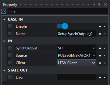
The last thing to be set is the “SH” trigger to the camera, for this we use the tool named SetupSynchOutput. The inputs of the tool are:
- SynchOutput: Depending on the controller model you may have several synch outputs; with this parameter you select which one to use. In our example, we are using “SH1”.
- Source: Select the activation source to trigger the activation of the camera output. In our example we will again use the “PG1” signal previously configured, then we set “PULSEGENERATOR1”.
- Client: Select which device do you want to access. Again, we are using the “LTDV Client” previously connected.
Please note that when this tool is executed by OEVIS, the synch output of the controller will start to generate the output trigger, and the camera will receive triggers to acquire images. Please refer to the camera manual to properly set its connections and parameters to grab images when input triggers are received.
With these four tools now, we have a setup where the LTDV controller is triggering a camera and a light at the same time. Some applications may require to properly set the overlap between the light emitted pulse and the camera exposure time by regulating their delays from the input triggers. This may happen due to different cables specifications. Note that by using the configuration proposed in this example, such delays cannot be configured by the LTDV controller, as both light and camera are synchronized to “PG1” signal, and no delays can be added on “LD3” or “SH1”. Then, in case a delay needs to be added, this can be introduced either by:
- the devices settings, typically the camera parameters allow to set it
- using two different pulse generated signals on the controller